
Table of Contents
ToggleIntroduction
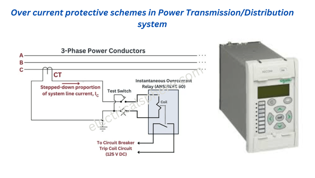
Power Transmission/Distribution system i.e. radial feeders uses overcurrent protection scheme. Feeder is divided in two or more section and one over current relay for each section is used.

If a fault occurs beyond C, the circuit breaker of section C trips and circuit breakers of section A and B must not trip in case of normal operation. But if the relay of section C fails to operate, the circuit breaker of section B should trip as a back-up protection.
Similarly, if a fault occurs between B and C, the circuit breaker of section B should trip and circuit breaker of section A should not trip. But if the relay of section B fails to operate, the circuit breaker of section A should trip.
Hence, it is clear that the relays must be selective with each other. For proper selectivity of the relays, different schemes are employed, depending on the system conditions.
Time graded overcurrent protection scheme

Definite time overcurrent relays are used by adjusting the operating time of relay in increasing order from the far end of the feeder to the source.
When fault occurs, it starts a timing unit that trips the circuit breaker after a preset time independent of the fault current.The difference in the time setting of two adjacent relays is usually kept at 0.5 s. This difference is to cover the operating time of the circuit breaker.
When a fault occurs beyond C, relays of all section come into action i.e. fault current flows through all of them. Relay placed in section C has least time setting, so it operates after 0.5 s and the fault is cleared. Once fault is cleared relays of section A and B are reset.
When relay or circuit breaker of section C fails i.e. fault remains uncleared. In this situation, after 1 s, the relay of section B operates that trips the circuit breaker of section B will trip. Somehow if the circuit breaker of section B also fails to operate, after 1.5 s, circuit breaker of section A trip.
Time graded over current protection scheme is preferred where the impedance (distance) between two substations is low i.e. fault current practically remains constant when fault occurs on any section of the feeder.
Current graded overcurrent protection scheme
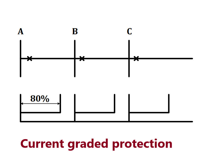
High speed instantaneous overcurrent relays are used by adjusting the pickup of relay in increasing order from the far end of the feeder to the source. Operating time of relay is kept same.
Based on relay pickup setting, relay of section B trips for faults between section B and section C but does not trip for fault beyond section C. This is theoretical presumption, in actual practice it may not happen because of several reasons such as
- It is difficult to determine amount of fault current accurately.
- Relay may not perform correctly during transient condition.
- Relay may not be able to discriminate the fault current when location of fault is end of section one and beginning of section two i.e. minute difference in magnitude of fault current.
Hence to get correct discrimination in current graded protection scheme, relays are set to protect about 80% of part of feeder. As this scheme does not protect entire feeder, it is used with IDMT relays.
Current graded over current protection scheme is preferred where the impedance (distance) between two substations is sufficient to create a margin difference in fault current.
Combination of Current and Time-grading
Inverse definite minimum time overcurrent (IDMT) relay has got time setting and current setting arrangement so they are the best suitable option for combined current and time graded scheme.
Relay current setting is carried out based on fault current level of equipment or section needs to be protected and set to pick up progressively at higher fault current levels towards the source.
Relay time setting is carried out progressively increasing order towards the source. The difference in operating times of two adjacent relays is kept 0.5 s.
Inverse time-current graded characteristics is required when source impedance and line impedance values have comprehensive difference. In this case when fault occurs at near end of line i.e. source magnitude of current is very high and when fault occurs at tail end i.e. feeder magnitude of current is low. For such situation, relay with inverse time-current characteristics trips faster for near end fault compared to fault at tail end.
Combined current and time graded scheme is used for distribution lines protection.

Pingback: What is Directional or reverse power relay and their working and application
Pingback: Directional overcurrent relay protection in Power system
Pingback: Types of Relay used in power system in detail - Electricalsphere
Pingback: Phase Overcurrent setting of Transmission line
I couldn’t resist commenting