
Table of Contents
ToggleWhat is D.G.A. ?
It is study of gases formed in the transformer oil. It is a diagnostic tool helping to detect faults by detecting abnormal changes in oil before Buchholz Relay responds.
DGA method has been used for several purposes: to detect incipient faults; to supervise suspect transformers; to test a hypothesis or explanation for the probable cause of failures or disturbances which have already occurred; and to ensure that new transformers are healthy.
DGA of transformer oil
For a new transformer before commissioning D.G.A. should be carried out , taking oil sample in steel bottle specially design for D.G.A. test and great care should be taken while taking oil sample for DGA.
There will be no any air pocket in sample bottle there is clear guide line for which transformer at which interval D.G.A. should taken . However any analysis can be carried out after study of previous D.G.A. test.
How to take oil sample for DGA test
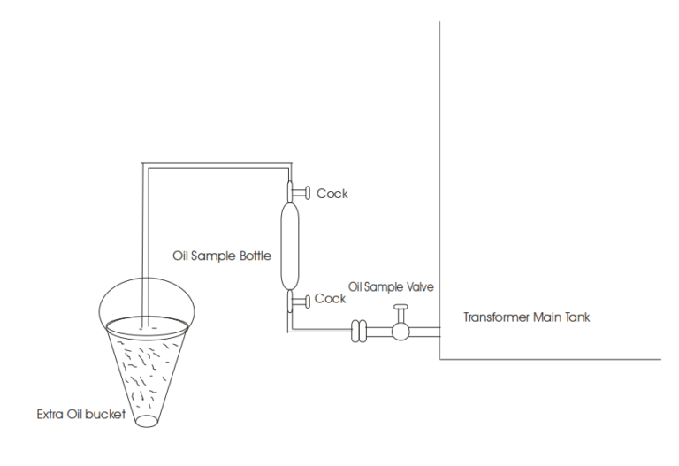
Take specially designed steel bottle for oil sample fill.
Identify oil sample valve in transformer and connect pipe with steel bottle.
Ensure no any air bubble present in oil sample.
Causes for the gas creation in transformer
Gases are generated by normal operation and aging, mostly H2 and CO with some CH4.
Operating transformers at sustained overload will generate combustible gases.
Problems with cooling systems, discussed in an earlier section, can cause overheating.
A blocked oil duct inside the transformer can cause local overheating, generating gases.
An oil directing baffle loose inside the transformer causes mis-direction of cooling oil.
Oil circulating pump problems (bearing wear, impeller loose or worn) can cause transformer cooling problems.
Oil level is too low; this will not be obvious if the level indicator is inoperative.
Circulating stray currents may occur in the core, structure, and/or tank.
An unintentional core ground may cause heating by providing a path for stray currents.
A hot-spot can be caused by a bad connection in the leads or by a poor contact in the tap changer.
A hot-spot may also be caused by discharges of static electrical charges that build up on shields or core and structures which are not properly grounded.
Hot-spots may be caused by electrical arcing between windings and ground, between windings of different potential, or in areas of different potential on the same winding, due to deteriorated or damaged insulation.
Winding and insulation can be damaged by faults downstream (through faults), causing large current surges through the windings. Through faults cause extreme magnetic and physical forces that can distort and loosen windings and wedges. The result may be arcing in the transformer, beginning at the time of the fault, or the insulation may be weakened and arcing develop later.
Insulation can also be damaged by a voltage surge such as a nearby lightning strike or switching surge or closing out of step, which may result in immediate arcing or arcing that develops later.
Insulation may be deteriorated from age and simply worn out. Clearances and dielectric strength are reduced, allowing partial discharges and arcing to develop. This can also reduce physical strength allowing wedging and windings to move extensively during a through-fault, causing total mechanical and electrical failure.
High noise level (hum due to loose winding) can generate gas due to heat from friction. Compare the noise to sister transformers, if possible. Sound level meters are available at the TSC for diagnostic comparison and to establish baseline noise levels for future comparison.
Sludge in the transformer and cooling system. Arcing due to clearance to the tank and to adjoining winding. Overheating of the joints in OLTC and brazed points.
Power flow through with continuous arcing . Inter turn winding failure . Shield ring failure. Core bolt fault . Overheating due to inadequate cooling or sustained over loading . Low energy sparking or partial discharges.
Permissible limit of dissolved gases in the oil of a healthy transformer
Gas | Less than four year | 4-10 years | Greater than 10 years |
Hydrogen H2 | 100/150 ppm | 200/300 ppm | 200 /300 ppm |
Methane CH4 | 50 /70 ppm | 100/150 ppm | 200/300 ppm |
Acetylene C2H2 | 20/30 ppm | 30/50 ppm | 100/150 ppm |
Ethylene C2H4 | 100/150 ppm | 150/200 ppm | 200/400 ppm |
Carbon | 200/300 ppm | 400/500 ppm | 600/700 ppm |
Carbon Dioxide | 3000/3500 ppm | 4000/5000 ppm | 9000/12000 |
Gas content in oil due to fault
Sr no | Type of Fault | Decomposable Gases |
1 | Arcing in oil | CH4 , C2 H4 |
2 | Over heating of solid insulating materials | CO , CO2 |
3 | Over heating of oil and paper combination | CH4, C2H2, CO, CO2 and H2 |
4 | Arcing of oil and paper combination | H2, C2H2, CO, CO2 |
Key Gas Method
Key Gas method becomes applicable to transformer with developed faults where absolute values of key gases are considered. The key gases are acetylene, hydrogen ,ethyleneand carbon monoxide. Following table illustrates the nature of faults, when key gas is abnormally high.
Key gas | Nature of Fault |
Acetylene C2H2 | Electrical arc in oil |
Hydrogen H2 | Corona , partial discharge |
Ethylen C2H4 | Thermal degradation of oil |
Carbon Monoxide | Thermal ageing of oil |
Table illustrates the various types of faults depending on the gas composition
Major Gas content | Minor Gas content | Nature of fault |
Ethylene | Ethane | Thermal Decomposition |
Methane | Hydrogen | Hot spots |
Hydrogen, Methane | Acetylene,Ethylene,Ethane | Electrical Discharge |
Hydrogen | Methane,Ethane | Internal Corona |
Carbon Monoxide,Carbon dioxide | Cellulosic insulation decomposition |
Rogers Ratio Method of DGA
Rogers Ratio Method of DGA is an additional tool that may be used to look at dissolved gases in transformer oil. Rogers Ratio Method compares quantities of different key gases by dividing one into the other. This gives a ratio of the amount of one key gas to another.
At certain temperatures, one gas will be generated more than another gas. Rogers used these relationships and determined that if a certain ratio existed, then a specific temperature had been reached. By comparing a large number of transformers with similar gas ratios and data found when the transformers were examined, Rogers could then say that certain faults were present.
Like the Key Gas Analysis above, this method is not a “sure thing” and is only an additional tool to use in analyzing transformer problems. Rogers Ratio Method, using three-key gas ratios, is based on earlier work by Doerneburg, who used five-key gas ratios.
Ratio methods are only valid if a significant amount of the gases used in the ratio is present. A good rule is: Never make a decision based only on a ratio if either of the two gases used in a ratio is less than 10 times the amount the gas chromatograph can detect.
Dissolved Gas Analysis Detection Limits in Roger ratio method
Hydrogen (H2) about 5 ppm
Methane (CH4) about 1 ppm
Acetylene (C2H2) about 1 to 2 ppm
Ethylene (C2H4) about 1 ppm
Ethane (C2H6) about 1 ppm
Carbon monoxide (CO) and carbon dioxide (CO2) about 25 ppm
Oxygen (O2 ) and nitrogen (N2) about 50 ppm
When a fault occurs inside a transformer, there is no problem with minimum gas amounts at which the ratio are valid. There will be more than enough gas present.
If a transformer has been operating normally for some time and a DGA shows a sudden increase in the amount of gas, the first thing to do is take a second sample to verify there is a problem. Oil samples are easily contaminated during sampling or at the lab.
If the next DGA shows gases to be more in line with prior DGAs, the earlier oil sample was contaminated, and there is no further cause for concern. If the second sample also shows increases in gases, the problem is real.
To apply Ratio Methods, it helps to subtract gases that were present prior to sudden gas increases. This takes out gases that have been generated up to this point due to normal aging and from prior problems. This is especially true for ratios using H2 and the cellulose insulation gases CO and CO2. These are generated by normal aging.
Rogers Ratio Method Uses the Following Three Ratios.
C2H2/C2H4, CH4/H2, C2H4/C2H6
These ratios and the resultant fault indications are based on large numbers of DGAs and transformer failures and what was discovered after the failures.
Advantage of DGA
Avoidance of unplanned outage as transformer defects are detected at incipient stages itself so that timely remedial measures can be undertaken to prevent damage or total loss of equipment.
Status of health check for transformer periodically
Is a quality test for new transformer /repaired transformer before dispatch, installation & commissioning
Cleaning transformer without internal faults, when they have tripped due to other reasons.
Several cases where transformer have been saved from total destruction, the confidence in DGA technique is so high that the transformers are sent to repairs by no other evidence other than that of DGA.
Pingback: Transformer Oil Properties and Characteristic - Electricalsphere
Thank you for your sharing. I am worried that I lack creative ideas. It is your article that makes me full of hope. Thank you. But, I have a question, can you help me?
what?