Table of Contents
ToggleNo load Test on 3-phase Induction Motor

This test is similar to OC test of transformer. It is used to determine constant losses in a induction motor and core loss component R0 and magnetising component X0 of equivalent circuit of Induction Motor.
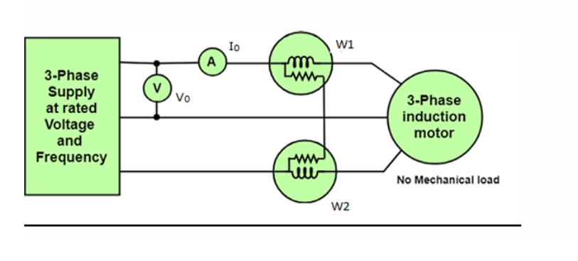
This test is conducted by giving rated voltage at rated frequency to the stator winding at no load condition as per the circuit diagram shown above. The voltmeter measures the rated supply voltage V0 and an ammeter measures the no-load current I0.
The two-watt meters give reading W1 and W2. Since the no load test is done at no load condition, the power factor of operation will be less than 0.5. So total power input at no load condition (W0) can be obtained by taking difference of W1 and W2. The no load input, W0 =core loss in stator+ friction and windage loss +copper loss in the stator (very small= 3𝐼02 𝑅1)
Calculations using NO load test values
W0=√3 V0 I0 cosΦ0
No load power factor, cosΦ0 = 𝑊0 /(√3 V0I0)
Iµ = I0 sinΦ0 Iω = I0 cosΦ0
𝑅0=𝑉𝑝ℎ /𝐼𝑤
𝑋0=𝑉𝑝ℎ /𝐼µ
𝑉𝑝ℎ = Input phase voltage
Locked Rotor Test or Blocked Rotor Test on 3-phase Induction Motor

This test is similar to SC test of a transformer . This test is used to find
- Short circuit current with normal voltage applied to stator
- Power-factor on short circuit
- Equivalent resistance and reactance of the motor referred to primary
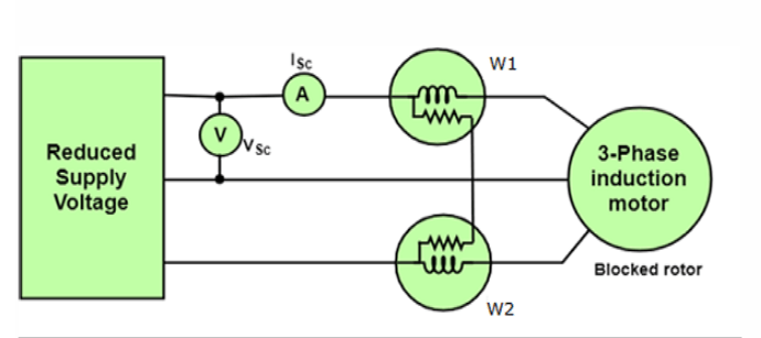
In this test rotor is locked or blocked and a reduced input voltage is applied to stator (VSC) till rated current is flowing in stator. The value of VSC will be 10 to 20% of rated stator voltage of IM. The ammeter measures value of short circuit current ISC and wattmeter measures total power input WSC in locked rotor conditions.
During this test, the stator carries the rated current hence the stator copper loss is also dominant. Similarly the rotor current also carries short circuit current to produce dominant rotor copper loss. As the voltage is reduced, the iron loss which is proportional to voltage is negligibly small. The motor is at standstill hence mechanical loss is absent. Hence we can write, WSC = Stator copper loss + Rotor copper loss
But it is necessary to obtain short circuit current when normal voltage is applied to the motor. This is practically not possible/ But the reduced voltage test results can be used to find ISN which is short circuit current if normal voltage is applied.
Calculations using Blocked rotor test values
Power factor on short circuit, cosΦsc= 𝑊SC /(√3 VSCISC)
Equivalent impedance per phase referred to stator,𝑍01 = 𝑉SC( 𝑝𝑒𝑟 𝑝ℎ𝑎𝑠𝑒)/ISC
Equivalent reactance per phase referred to stator X01 =√(𝑍012 − 𝑅012)
High torque rotors of Induction Motor
In case of slip ring IM, an external resistance can be added in the rotor circuit during starting which gives higher starting torque and lower starting line current at an improved power factor. This resistance is then gradually cut from the rotor circuit which would otherwise result in decrease of full load speed, poor speed regulation, more rotor losses and hence reduced efficiency. This is the major advantage of slip ring IM that it gives high rotor resistance during starting and low rotor resistance during normal operating speed.
In case of squirrel cage IM, there is no provision for adding external resistance. If the resistance is designed in such a way that it has high starting current and consequently low starting torque. This is major disadvantage of squirrel cage IM although it is having the other qualities of low cost, ruggedness and maintenance free operation.
In squirrel cage IM high starting torque can be obtained by the use of deep bar or double cage rotors. Both these types of make use of skin effect in which distribution of current is not uniform but the alternating current has the tendency to concentrate near the surface of the conductor. Due to this effect, effective area of cross-section of the conductor is reduced and hence the resistance of the conductor is increased when carrying alternating current.
The solid conductor can be considered to be made up of large number of strands each carrying a small part of current. The inductance of each strand will vary according to the position. The strands in proximity of the centre are surrounded by greater magnetic flux and have higher inductance than near the surface.
Due to high reactance at the centre, the alternating current flows near the surface of the conductor. The skin effect depends upon the nature of material, diameter of the wire, shape of the wire and frequency.
Thus the current in the rotor during starting is having the frequency of the supply. While under running condition the frequency of the rotor current reduces to slip frequency. This variation in frequency changes the rotor resistance as it depends on the skin effect.
During starting it gives high resistance whereas it gives low resistance during normal condition which is desirable. Thus the variation in rotor resistance can be achieved by deep bar or double cage construction of rotor of IM.
