
A normal synchronous motor rotor having a damper winding arranged such like slip ring IM. On applying 3-phase supply to the armature winging of Synchronous motor, its start as an induction motor(IM).
On achieving about 95% of synchronous speed, the rotor winging is connecter to exciter terminal (by changeover) and rotor is magnetically locked with stator r.m.f. and motor runs as a synchronous motor.
If starting and excitation is done automatically the motor is known as Auto-Synchronous Motor.
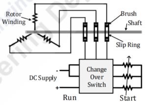
Fig. shows the circuit diagram of Auto Synchronous motor rotor.
In this method synchronous motor start as a Slip Ring IM.
This method of starting used when synchronous motor started ON Load.
Modified Rotor winding (Three phase winding) just like slip ring induction rotor are placed in rotor face/slot and brought out through slip ring & connect with variable resistant (Fig.)
Hence, rotor start rotating just like induction motor and reached very near to synchronous speed. As rotor reached near to synchronous speed, change over switch will operate from start position to run potion & DC supply apply to the field winding.
Due to this stator pole attract the rotor pole and magnetic locking (synchronism) take place automatically. As changeover take place, slip ring winding get DC excitation. Hence, starting winding has now became field winding after starting period.
By variable resistance, High starting torque and Less Starting Current can obtain. Motor can start on load.
Rekabetçi fiyatlar SEO çalışmaları sayesinde web sitemizin trafiği katlandı. https://www.royalelektrik.com//esenyurt-elektrikci/
YouTube abone SEO optimizasyonu ile web sitemiz daha fazla ziyaretçi çekmeye başladı. https://royalelektrik.com/blog/
Pingback: Hunting in Synchronous Motor and Cause of Hunting - Electricalsphere
Pingback: Types of Railway Track Electrification
I enjoy your work, thankyou for all the informative content.
I am now not positive the place you’re getting your information, but great topic. I needs to spend some time finding out more or figuring out more. Thank you for fantastic info I was on the lookout for this information for my mission.
Great write-up, I am regular visitor of one’s web site, maintain up the excellent operate, and It is going to be a regular visitor for a long time.
I got good info from your blog
Hi there would you mind stating which blog platform you’re working with? I’m planning to start my own blog soon but I’m having a hard time deciding between BlogEngine/Wordpress/B2evolution and Drupal. The reason I ask is because your design and style seems different then most blogs and I’m looking for something completely unique. P.S Sorry for getting off-topic but I had to ask!
i used wordpress for my website. Best of luck for your future website.
For more electrical Knowledge, Please follow my Insta/Telegram/Whatsapp group.
To boost my moral, Please share my website to your friends.
Pingback: Types of synchronous motor starters - Electricalsphere
Your article helped me a lot, is there any more related content? Thanks!