
Table of Contents
ToggleCapacitor Unit

The capacitor unit, Fig-A, is the building block of a shunt capacitor bank. The capacitor unit is made up of individual capacitor elements, arranged in parallel/ series connected groups, within a steel enclosure. The internal discharge device is a resistor that reduces the unit residual voltage to 50V or less in 5 min. Capacitor units are available in a variety of voltage ratings (240 V to 24940V) and sizes (2.5 kvar to about 1000 kvar).
Capacitor unit capabilities
Relay protection of shunt capacitor banks requires some knowledge of the capabilities and limitations of the capacitor unit and associated electrical equipment including: individual capacitor unit, bank switching devices, fuses, voltage and current sensing devices.
Capacitors are intended to be operated at or below their rated voltage and frequency as they are very sensitive to these values; the reactive power generated by a capacitor is proportional to both of them (kVar ≈ 2π f V 2 ).
These standards stipulate that:
Capacitor units should be capable of continuous operation up to 110% of rated terminal rms voltage and a crest voltage not exceeding 1.2 x √2 of rated rms voltage, including harmonics but excluding transients. The capacitor should also be able to carry 135% of nominal current.
Capacitors units should not give less than 100% nor more than 115% of rated reactive power at rated sinusoidal voltage and frequency.
Capacitor units should be suitable for continuous operation at up to 135%of rated reactive power caused by the combined effects of: a) Voltage in excess of the nameplate rating at fundamental frequency, but not over 110% of rated rms voltage. b) Harmonic voltages superimposed on the fundamental frequency. c) Reactive power manufacturing tolerance of up to 115% of rated reactive power.
Shunt Capacitor Bank Configurations
The use of fuses for protecting the capacitor units and it location (inside the capacitor unit on each element or outside the unit) is an important subject in the design of SCBs. They also affect the failure mode of the capacitor unit and influence the design of the bank protection. Depending on the application any of the following configurations are suitable for shunt capacitor banks:
Externally Fused Shunt capacitor bank
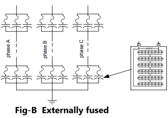
An individual fuse, externally mounted between the capacitor unit and the capacitor bank fuse bus, typically protects each capacitor unit. The capacitor unit can be designed for a relatively high voltage because the external fuse is capable of interrupting a high-voltage fault. Use of capacitors with the highest possible voltage rating will result in a capacitive bank with the fewest number of series groups.
A failure of a capacitor element welds the foils together and short circuits the other capacitor elements connected in parallel in the same group. The remaining capacitor elements in the unit remain in service with a higher voltage across them than before the failure and an increased in capacitor unit current.
If a second element fails the process repeats itself resulting in an even higher voltage for the remaining elements. Successive failures within the same unit will make the fuse to operate, disconnecting the capacitor unit and indicating the failed one. Externally fused SCBs are configured using one or more series groups of parallel-connected capacitor units per phase (Fig-B).
The available unbalance signal level decreases as the number of series groups of capacitors is increased or as the number of capacitor units in parallel per series group is increased. However, the kiloVar rating of the individual capacitor unit may need to be smaller because a minimum number of parallel units are required to allow the bank to remain in service with one fuse or unit out.
Internally Fused Shunt capacitor bank
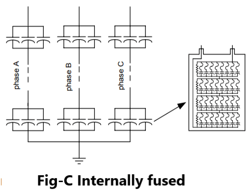
Each capacitor element is fused inside the capacitor unit. The fuse is a simple piece of wire enough to limit the current and encapsulated in a wrapper able to withstand the heat produced by the arc. Upon a capacitor element failure, the fuse removes the affected element only. The other elements, connected in parallel in the same group, remain in service but with a slightly higher voltage across them.
Fig-C illustrates a typical capacitor bank utilizing internally fused capacitor units. In general, banks employing internally fused capacitor units are configured with fewer capacitor units in parallel and more series groups of units than are used in banks employing externally fused capacitor units. The capacitor units are normally large because a complete unit is not expected to fail.
Fuseless Shunt Capacitor Banks
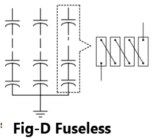
The capacitor units for fuseless capacitor banks are identical to those for externally fused described above. To form a bank, capacitor units are connected in series strings between phase and neutral, shown in Fig-D.
The protection is based on the capacitor elements (within the unit) failing in a shorted mode, short- circuiting the group. When the capacitor element fails it welds and the capacitor unit remains in service. The voltage across the failed capacitor element is then shared among all the remaining capacitor element groups in the series.
For example, is there are 6 capacitor units in series and each unit has 8 element groups in series there is a total of 48 element groups in series. If one capacitor element fails, the element is shortened and the voltage on the remaining elements is 48/47 or about a 2% increase in the voltage. The capacitor bank continues in service; however, successive failures of elements will lead to the removal of the bank.
The fuseless design is not usually applied for system voltages less than about 34.5 kV. The reason is that there shall be more than 10 elements in series so that the bank does not have to be removed from service for the failure of one element because the voltage across the remaining elements would increase by a factor of about E (E – 1), where E is the number of elements in the string.
The discharge energy is small because no capacitor units are connected directly in parallel. Another advantage of fuseless banks is that the unbalance protection does not have to be delayed to coordinate with the fuses.
Unfused Shunt Capacitor Banks
Contrary to the fuseless configuration, where the units are connected in series, the unfused shunt capacitor bank uses a series/parallel connection of the capacitor units. The unfused approachwould normally be used on banks below 34.5 kV, where series strings of capacitor units are not practical, or on higher voltage banks with modest parallel energy. This design does not require as many capacitor units in parallel as an externally fused bank.
Pingback: Capacitor Bank Protection - Electricalsphere
Thanks for any other informative site. Where else could I get that kind of info written in such an ideal method? I have a challenge that I’m simply now operating on, and I’ve been on the glance out for such info.
I am curious to find out what blog platform you happen to be utilizing? I’m experiencing some minor security problems with my latest site and I would like to find something more secure. Do you have any recommendations?
Greetings! Quick question that’s totally off
topic. Do you know how to make your site mobile
friendly? My web site looks weird when browsing from my iphone.
I’m trying to find a template or plugin that might be able to
correct this problem. If you have any recommendations, please share.
Thank you!
Feel free to surf to my web site … nordvpn coupons inspiresensation – http://tinyurl.com/ –
Oh my goodness! an incredible article dude. Thank you Nevertheless I am experiencing situation with ur rss . Don’t know why Unable to subscribe to it. Is there anybody getting equivalent rss problem? Anyone who is aware of kindly respond. Thnkx
hi,
thanks for appreciation. Now, my focus on spread my website content to more readers.
To boost my moral, Please share my website to your friends and subscribe my Insta/Telegram/Whatsapp group.