Table of Contents
ToggleWhat is function of Isolator?
Isolator may be defined as a mechanical switch which isolates a part of the circuit from the system as and when required.
Electrical isolators separate a part of the system from rest for safe maintenance works. Isolators are used to open a circuit under no load.
Its main purpose is to isolate one portion of the circuit from the other and is not intended to be opened while current is flowing in the line(on load).
Isolators are generally used on both ends of the breaker so that repair or replacement of circuit breaker can be done without any danger.
In high-voltage power systems, isolators are use in conjunction with circuit breakers to provide an extra layer of safety.
Construction of Isolator
Isolators used for power systems are three pole isolators.
All the poles are identical and operated by a single mechanism and mechanical interlocking.
Each pole has a fabricated support on which two or three insulator posts are mounted.
The live part which is used for isolation is supported on the insulator posts
The live part has a conducting copper or aluminium rod with fixed or moving contacts
When the moving part is operated, the conducting rods move apart to achieve isolation.
Isolator Operation
Isolators must be opened after circuit breaker is open, and these must be closed before circuit breaker is closed.
The isolator can be operated by hand locally as well as by motorized mechanism from a remote position.
Motorized operation arrangement costs more compared to hand operation; hence decision must be taken before choosing an isolator for the system whether hand operated or motor operated economically optimum for the system.
For voltages up to 145 KV system hand operated isolators are used whereas for higher voltage systems like 245 KV or 420 KV and above motorized isolators are used.
Types of Isolator
Horizontal Break ( normally Double break)
Vertical Break (normally single break)
Pantograph type
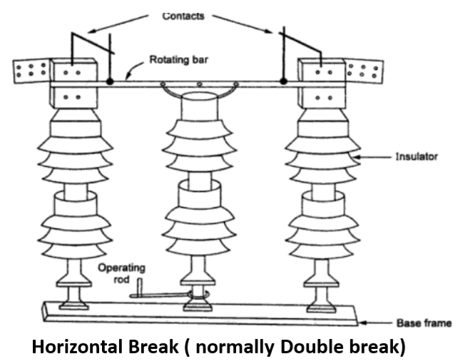
Horizontal Break ( normally Double break) Isolator

Construction of Horizontal Break ( normally Double break)
Fig. shows the schematic diagram of a horizontal double Break Isolators. It consists of three insulator stacks per pole. Two stacks on each side are fixed. The stack at the center is rotating one. The central stack can swing about its vertical axis through about 90 degrees.
The central post insulator carries a tubular or flat moving contact which can be rotated horizontally with a rotation of central post insulator. The fixed type contacts are fixed on the top of the other two post insulators . The fixed contacts are generally in the form of spring-loaded figure contacts.
The rotational movement of moving contact causes to come itself into fixed contacts and isolators becomes closed. The rotation of moving contact in the opposite direction make it to come out from fixed contacts and isolators become open.
Operation of Horizontal Break ( normally Double break)
Fixed contacts of metal are supported on stack of insulator. Moving contact rod is connected to central insulating support which can be moved to have horizontal movement for opening or closing into the fixed contacts.
The movement of the rod and its support may be done manually, electrically or pneumatically by operators. The operating mechanism disengages or engages the rod into fixed contacts for closing and opening of isolator.
The moving contact’s movement is horizontal and hence this type of isolator is named as horizontal break isolator. The rod contact can be moved through 90 degrees.
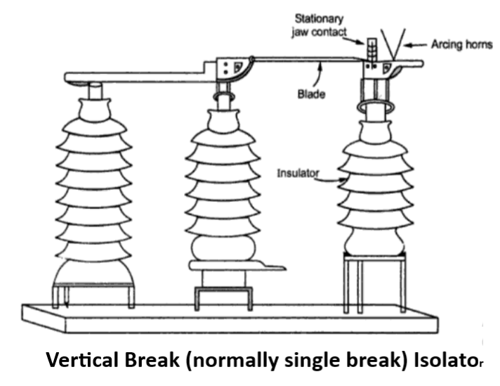
Vertical Break (normally single break) Isolator

The vertical break type isolators consists of a fixed contact and a rotating switch blade( moving contact). The rotating switch is supported by middle or the central post, whereas the fixed contact is mounted on the top of the right most post.
During opening and closing, the switch blade vertically moves in or out of the fixed contact. The fixed contacts are silver surfaced and lock the blade in place by increasing pressure on the switch blade during momentary current flow.
Constant pressure is maintained by insulated stainless steel back up springs. The arcing horns divert the current from primary contact and eliminates contact pitting and erosion.
Pantograph type Isolator

Pantograph is a mechanical linkage connected in a manner based on parallelograms so that the movement of one pen, in tracing an image, produces identical movements in a second pen. If a line drawing is traced by the first point, an identical enlarged, or miniaturized copy will be drawn by a pen fixed to the other.
Construction of Pantograph type Isolator
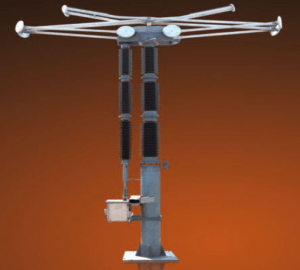
The Pantograph isolators are single break and vertical reach type . The pantograph mechanism is installed on the support insulator and transfers the movement of the operating rod insulator to the bars.
The movement mechanism is housed in an Aluminium enclosure, protecting it from pollution and ice. Pantograph bars are built using light tubes made of aluminium magnesium alloy. It has high mechanical strength and very good conductivity.
Due to the high elasticity of the material, pantograph construction is flexible. The upper pantograph bars are fitted with silver plated contact strips. The lower bars are connected to the bottom aluminium housing fitted on the supporting insulator post.
The current transfer takes place from the top bus bar to the bottom bus bar through through four arms . Pantograph isolators cover less floor area. These are used at ultra high voltage substations.
Operation of Pantograph type Isolator
In the closed position, the upper two arms of the pantograph close on the overhead bus bar giving a grip. The conducting pantograph bars carry the current from the upper bus bar to the lower bus bar.
To open the contacts the rotary insulator is rotated about its axis. The pantograph arms collapse in vertical plane and the vertical isolation is achieved between the line terminal and the pantograph upper terminal. By rotating the insulator column in the opposite direction, the linkage of the pantograph are brought nearer while closing it again.
Application of Isolator
Isolating the equipment from the buses for maintenance purpose.
Sectionalizing the buses
Bypassing the buses
Transferring loads

Pingback: 11kV/400V Pole mounted sub-station - Electricalsphere
Pingback: Types of Bus Bar Scheme in Electrical Substation
We’re a group of volunteers and starting a new scheme in our community. Your site provided us with valuable info to work on. You have done an impressive job and our whole community will be grateful to you.
If you want high-purity THCA Isolate Powder without breaking the bank, this is the best place to order!
Need high-quality THCA Isolate Powder? It’s lab-tested and perfect for those who want pure potency.
F*ckin?awesome issues here. I am very satisfied to see your article. Thank you a lot and i’m taking a look forward to contact you. Will you kindly drop me a e-mail?