
Table of Contents
ToggleDefine GIS
Gas-insulated substations (GIS) are electrical substations where high-voltage electrical equipment is enclosed in a sealed environment filled with insulating gas, such as sulphur hexafluoride (SF6), to minimize size and enhance safety.
Need of GIS- Gas Insulated Substation
- Space efficiency: GIS allow for compact installations in urban areas or locations with limited space availability.
- Enhanced safety: Encapsulation of high-voltage components reduces the risk of electrical hazards and protects against environmental factors.
- Reduced environmental impact: SF6 gas insulation minimizes greenhouse gas emissions and prevents atmospheric pollution.
- High reliability: Sealed enclosures prevent moisture ingress and ensure stable operation in harsh environmental conditions.
- Lower maintenance requirements: GIS systems require less maintenance compared to airinsulated substations due to reduced exposure to external elements.
- Increased security: Protection against vandalism and unauthorized access is improved with sealed enclosures and advanced monitoring systems.
Essential Parts of GIS
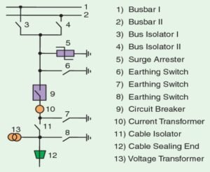
Busbar, Circuit Breaker, Disconnector (line or bus), Earthing switch (line or bus), Current transformer (feeder / bus), Voltage transformer (feeder / bus), Feeder Disconnector, Feeder Earthing switch , Lightning / Surge Arrester, Cable termination, Control Panel
Why higher cost of GIS compared to Conventional Substation?
Reason behind higher cost of GIS substation:
In the GIS system, all the live components are enclosed in a grounded metal enclosure, and then the whole system is housed in a chamber full of gas, which results in the increase in cost.
Whole substation is assembled in closed constructed building, which increases the cost.
Care should be taken that no dust particles enter into the live compartments which results in flashovers. So sealed compartments are required, which results in the increase in cost.
SF6 gas pressure must be monitored in each compartment, reduction in the pressure of the SF6 gas in any module results in flash overs. The monitoring system results in the increase in cost.
Importance of partial discharge monitoring system for the GIS substation
1) Finding a problem quickly: The monitor will identify a problem in its earliest stages of defect development. This will provide one with sufficient information as to the growth rate and the severity of the defect.
2) Providing information as to which phase the defect is in and generally what type of defect: Defects such as Corona Surface Discharge, Void type of defect (Insulation Delamination), Conductive tape deterioration (Slot Discharge), loose high voltage connection that is arcing, are informed. It is even possible to localize even further the location of the defect.
3) Since no labor is required to perform the tests, continuous monitoring allows the use of limited resources for finding solutions to problems instead of finding problems.
4) Reducing unnecessary maintenance because the monitor will be constantly testing and will have accurate data on which to base decisions.
5) Collecting more accurate data as tests are conducted under real operating condition.
6) Requiring no outage to perform the test, therefore there is no loss of asset productivity.
7) No introduction of infant mortality failure patterns via more invasive testing procedures.
8) Reduction of forced outages and increased safety of personnel. One will always be aware of conditions and/or problems.
9) Correlation of other dynamics such as temperature, humidity and load current to PD activity, which provides additional insight for diagnostics. There will be no need to go to several sources and gather the information.
10) Provides the opportunity for remote diagnostics. The expert does not need to come out to the field for basic diagnostics. A site visit by an expert will be the exception and not the rule. This can be done my emailing data to an expert or perhaps have a modem connected to the monitor so the expert can dial-in and upload the information for analysis and even provide a special test if necessary.
11) Evaluation of a piece of equipment is based on its own history and not by comparison to other equipment. This will make the detection of subtle problems easier.
12) Easily monitor worsening conditions so one can defer repairs and allow time to plan an outage.
Operation of circuit breaker in GIS
The circuit breaker is the most critical part of a gas insulated substation system. The circuit breaker in a gas insulated system is metal-clad and utilises SF6 gas, both for insulation and fault interruption.
The SF6 gas pressure in a circuit breaker is around 0.65 MPa.
At the core of the gas insulated switchgear is the interrupter unit which is housed in the circuit breaker module. It operates on a modern self compression principle. The current path consists of a base, a movable contact cylinder and a contact carrier in closed position.
The operating current flows through the main contact and through the contact cylinder. During the breaking of operating currents the main contacts opens first but the current still commutes through the arcing contact which remains closed at this stage of the switching process, this avoids erosion of the main contact.
During the further course of opening the arcing contacts open and an electric arc is drawn between the arcing contacts at the same time the contact cylinder moves into the base and compresses the arc quenching SF6. This gas compression generates a gas flow through the contact cylinder and the nozzle to the arcing contact. This way the arc is extinguished.
Operation of disconnecting switch in GIS:
Disconnectors (or disconnect switches) are placed in series with the circuit breaker to provide additional protection and physical isolation. In a circuit, two disconnectors are generally used, one on the line side and the other on the feeder side. Disconnect switches are designed for the interruption of small currents, induced or capacitively coupled.
Disconnecting switches can be motorized or driven manually. In GIS system, motorized isolators are preferred. A pair of fixed contacts and a moving contact form the active parts of disconnect switch. The fixed contacts are separated by an isolating gas gap. During the closing operation, this gap is bridged by the moving contact.
The moving contact is attached to a suitable drive, which imparts the desired linear displacement to the moving contact at a pre-determined design speed. A firm contact is established between the two contacts with the help of spring-loaded fingers or the multi-lam contacts. The isolation gap is designed for the voltage class of the isolator and the safe dielectric strength of the gas.
An insulator is used to drive the moving contact and to isolate the drive from the high voltage components of the disconnector. The shape and size of the insulator are controlled by the electrical and mechanical requirements of the isolator. In three-phase ac systems, the individual phase isolators are ganged together to operate simultaneously.
Leak-tight rotary seals are used in gas insulated isolators for transferring motion from external drive to the gas. Disconnectors in high voltage GIS operate at SF6 pressures of 0.38 MPa to 0.45 MPa. The operating speed of the disconnector moving contact ranges from 0.1 to 0.3 m/sec. This is how disconnectors are operated inside SF6 filled switchgears (GIS).
Advantages and drawback of GIS
Advantages of GIS substation
Space required is less i.e. 1/10th of conventional substation
GIS are very safe & operating personnel are protected by the earthed metal enclosure.
Most reliable compared to air insulated substation.
Weight is very less due to aluminium enclosure used.
No pollution.
Dielectric strength of SF6 Gas is 3 times the dielectric strength of air.
Time of erection is less as assembled parts are used.
Drawbacks of GIS Substation
High initial investment: Gas-insulated substation (GIS) involves significant capital expenditure due to the specialized equipment and technology required.
Limited space flexibility: GIS have less flexibility for expansion or modifications due to the compact design and fixed infrastructure.
Maintenance challenges: Maintenance of GIS equipment can be complex and costly due to the need for specialized personnel and equipment.
Environmental concerns: SF6 is a strong greenhouse gas with a high global warming potential. Leakage or improper handling of SF6 during installation, maintenance, or decommissioning can contribute to environmental pollution.
Transportation difficulties: Transporting GIS components to remote or inaccessible locations can be challenging due to their size, weight, and delicate nature.
Limited expertise: GIS technology requires specialized knowledge and expertise for design, installation, and maintenance.
I like what you guys are up also. Such smart work and reporting! Keep up the superb works guys I have incorporated you guys to my blogroll. I think it will improve the value of my web site 🙂
Pingback: GIS Substation Maintenance and Verification schedule - Electricalsphere
Pingback: Tripping of 220kV Feeder on SF6 lockout declaration in GIS Substation - Electricalsphere