
Table of Contents
ToggleWhy Bus Bar Protection required?
Busbars in the substation form important link between the incoming and outgoing circuits. If a fault occurs on a busbars, considerable damage and disruption of supply will occur unless some form of quick-acting automatic protection is provided to isolate the faulty busbar.
The busbar zone, for the purpose of protection, includes not only the bus bars themselves but also the isolating switches, circuit breakers and the associated connections. The two most commonly used schemes for busbar protection are
- Differential protection
- Under voltage protection.
- Over- current protection with directional element.
- Combined Earth fault and phase fault protection.
- Frequency relay.
Differential protection in Bus bar
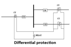
The basic method for busbar protection is the differential schemes in which current entering and leaving the bus are totalised. During normal load condition, the sum of these currents is equal to zero. When a fault occurs, the fault current upsets the balance and produces a differential current to operate a relay.
Under normal load condition or external fault condition, the sum of the current entering the bus is equal to those leaving it and no current flows through the relay. If a fault occurs within the protective zone, the currents entering the bus will no longer be equal to those leaving it. The difference of these currents will flow through the relay and cause the operation of the each of the circuit breaker.
Under voltage Protection relays
Under voltage protection is provided for bus-bars, rectifiers, transformers etc. such protection is given by means of under voltage relays. Under voltage relays are necessary for voltage control and reactive power control of network buses and load buses. Under voltage relays can have instantaneous characteristic or inverse characteristic depending upon the construction and design. Inverse time under voltage relays have inverse characteristic, their operating time reduces with reduction in voltage. Induction disc type construction is used for inverse under voltage relay.
Combined earth fault and phase fault protection
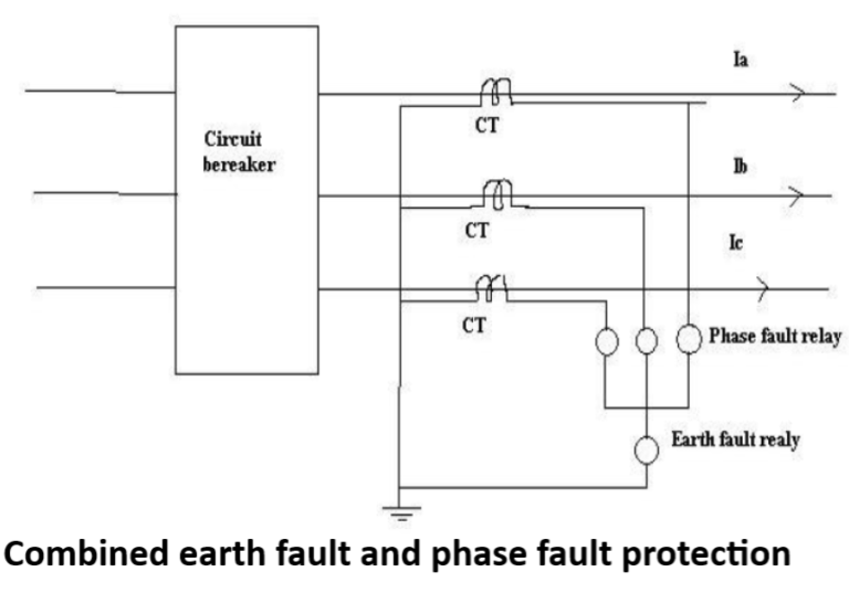
It is convenient to incorporate phase fault and earth fault relay in a combined phase fault and earth fault protection. The earth relay has low current setting and operates under earth or leakage faults only. The overload relays have high current setting and are arranged to operate against faults between the phases.
In the absence of earth fault the vector sum of three line currents is zero. Hence the vector sum of three secondary currents is also zero. Ias+Ibs+Ics=0 so during normal condition no current flows through earth fault relay and the relay will not operate. However in the presence of earth fault the condition is disturbed and Ias+Ibs+Ics≠0 , so the current flows through earth fault relay and if this current is above the pickup value, relay operates.
For any phase-phase fault the increase in current of phase cause corresponding increase in respective secondary current. If the current becomes more than pickup current , relay operates.
Directional power relay
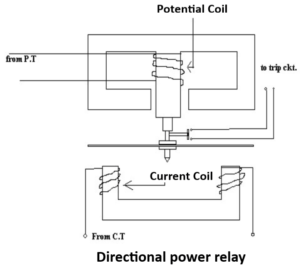
This type of relay operates when power in the circuit flows in a specific direction. A directional power relay is so designed that it obtains its operating torque by the interaction of magnetic fields derived from both voltage and current source of the circuit it protects. In this type of relays, Torque developed α VI cosфα power in the circuit.
When the power in the circuit flows in the normal direction, the driving torque and the restraining torque help each other to turn away the moving contact from the fixed contacts. Consequently, the relay remains inoperative. However reversal of current in the circuit reverses the direction of driving torque on the disc.
Enjoyed reading this, very good stuff, thankyou. “A man does not die of love or his liver or even of old age he dies of being a man.” by Percival Arland Ussher.
Pingback: Distance relay Zone of Protection - Electricalsphere
Excellent overview
Your point of view caught my eye and was very interesting. Thanks. I have a question for you. https://accounts.binance.info/en-ZA/register-person?ref=B4EPR6J0