
Table of Contents
ToggleDifferential Relay Insulation Testing
Connect together all relay C.T. terminals and measure the insulation resistance between these terminals and all of the relay terminals connected together and to earth.
Connect together the terminals of the DC auxiliary supply (only +ve and -ve) and measure the insulation resistance between these terminals and all of other terminals connected together and to earth.
Connect together all the output relay terminals and measure the insulation resistance between these terminals and all of other terminals connected together and to earth.
Satisfactory values for the various readings depend upon the amount of wiring concerned. Where considerable multi-core wiring is involved a reading of 2.5 to 3.0 meg ohms can be considered satisfactory. For short lengths of wiring higher values can be expected. A value of 1.0 meg ohm should not be considered satisfactory and should be investigated.
Relay Secondary Injection Testing
Select the required relay configuration and settings for the application. Note that the MIB202 relay can be connected either as 1A or 5A-rated device. The user should check this before commencing secondary testing.
Checking the bias Characteristics
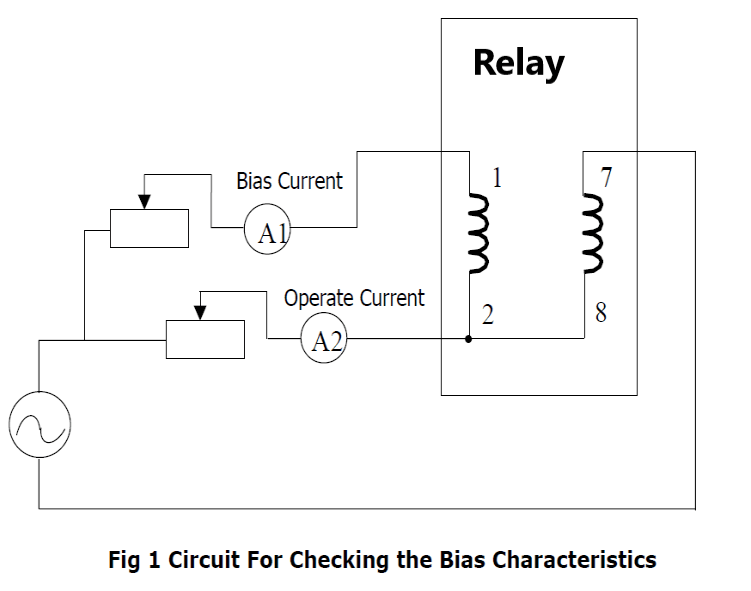
To check the bias characteristics using the simple single-phase test circuit shown in fig 1. The relay must be set as follows:
Initial setting is to be the same value as bias slope
HV Interposing CT multiplier 1.00
HV Interposing CT connections Yy0
LV Interposing CT multiplier 1.00
LV Interposing CT connections Yy0
The adjustable resistors in the test circuit should be chosen so that the injected current can be easily controlled over the range of20 % to 250 % of In.
Refer to fig 1. With zero bias current (ammeter A1=0), inject operate current in to phase A. When the relay operates, shown by the LED “Trip” illuminating, record the value of the current indicated on ammeter A2.
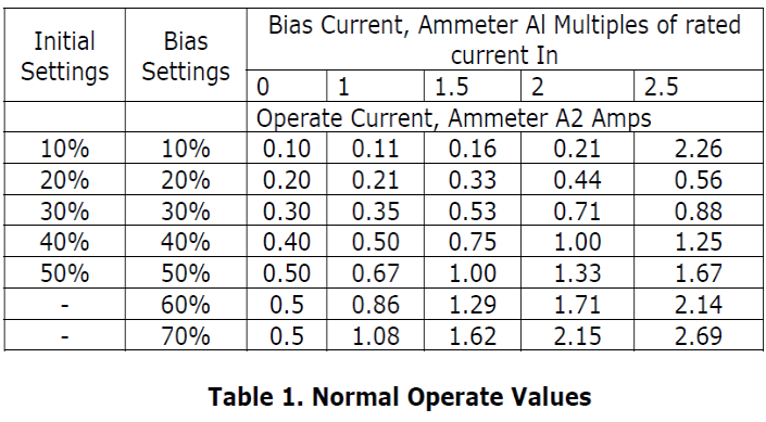
Repeat the test with increasing bias currents up to 2.5 times the relay rating.
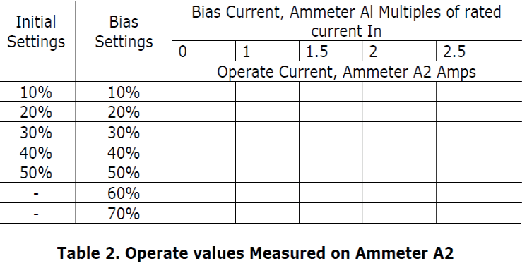
Record the results obtained in Table 2 and compare with the nominal values in Table 1.
Repeat the test for the other phases.
Output Relays
Trip – 1 N/O contacts (13 & 14, 15 & 16)
This contact to be used whiles testing the Bias characteristic and Highset of the relay.
Biased Differential – 1 N/O Contact (17 & 19)
This contact to be used whiles testing the Bias characteristic and of the relay.
Differential Highset – 1 N/O contact (17 & 20)
This contact to be used while testing the highset characteristic.
Protection Unhealthy – 1 N/C contact (17 & 18)
Primary Injection
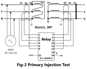
Primary injection is needed however to verify the secondary connection of a neutral CT relative to the phase CT’s and the relay. In these primary current must be injected through the associated power transformer winding. It may be necessary to short-circuit another winding in order to allow current to flow. Refer Fig-2.
During these primary injection tests the injected current is likely to be small due to the impedance of the transformer. Measure the phase current and neutral spill current.
CT Ratio and Polarity Tests
These tests check the ratio and polarity of the star connected CT’s with or without a neutral CT and also their connections to the correct terminals of the relay input modules
Relay put into Service
After completing all tests satisfactorily, the relay should be put back into service as follows:
- Make a final check of the secondary wiring and tightness of all terminal connections.
- Insert the DC supply fuse.
- Check the relay healthy indication/display.
- Replace the relay cover.
- Insert the trip links.
- Perform trip test by secondary injection.
- Remove all test connections

I don’t think the title of your article matches the content lol. Just kidding, mainly because I had some doubts after reading the article.