
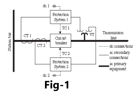
Consider the relay connections in Figure-1, which might be considered the maximum practical redundancy in relay connections. Note that there are two independent relay systems, each of which could contain several relays to detect phase and ground faults on the protected line section.
This system is made very reliable by the use of completely independent systems for
dc power supply (batteries)
secondary potential supply to each relay system
current monitoring for each relay system
dual trip coils in the circuit breaker
Dual communications systems to the remote end of the line can also be provided. In most cases for high voltage systems, the two systems are functionally equivalent protection systems typically named “Protection System 1” and “Protection System 2,” or “System A” and “System B.” In other cases, particularly for lower voltage systems, one system may not have all the selectivity, speed, or sensitivity of the other. In those cases, the systems will be named the “primary” and the “backup” systems.
The redundancy in Figure-1 is not uncommon, except for the redundant battery, which may only be specified at critical locations. Note that all system functions are duplicated except the primary of the voltage transformer and the circuit breaker. The primary of the voltage transformer is normally regarded as sufficiently reliable or available so that redundancy is not required. The independent secondary windings of the voltage transformer are separately protected so that a short circuit on one secondary does not affect the other. As far as the circuit breakers are concerned, it would be possible to place redundant circuit breakers in series and have them controlled by independent relays. This would be very costly and would probably not even be considered except for a circuit that is considered very important for some reason.
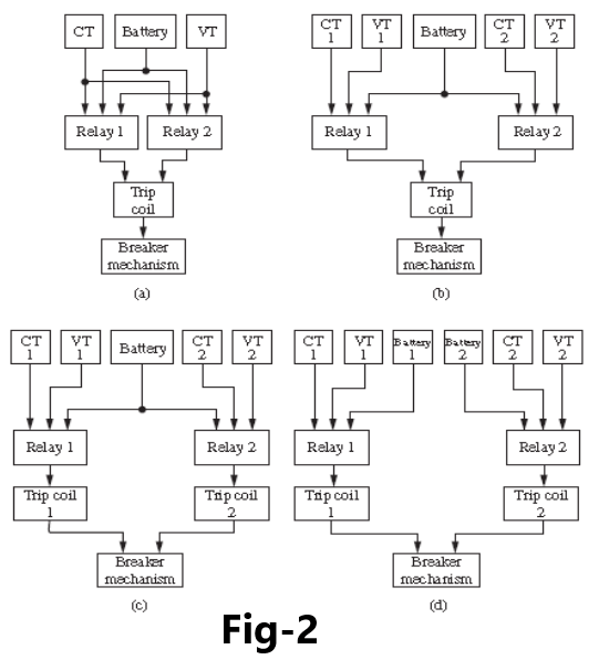
Figure-2 shows control configurations that are commonly used in power system protection.
Part (a) has redundancy only in the relays and the two relay systems share the same battery and the same instrument transformers.
In part (b), the system is made more reliable by duplicating the instrument transformers, giving each relay its own independent supply. This leaves the circuit breaker trip coil and breaker mechanism to be the most vulnerable to failure of the protective system.
Part (c) of Figure-2 uses duplicate trip coils and has each relay connected to its own trip coil. Since the added trip coil can be obtained at quite a reasonable cost, this is often considered to be prudent, especially for the higher voltage circuits that carry large amounts of power. On these circuits, failure to properly clear a fault can have very high cost and hence greater redundancy is readily justified.
Part (d) of Figure-2 uses redundancy in all subsystems except the circuit breaker mechanism, which would be very expensive to duplicate. This arrangement would be used at stations where high reliability is very important. Obviously, other control configurations can be devised. It is not likely that a utility would use the same configuration for all applications, since the protected circuits are not equally important to the integrity of the entire system. Generally, the high-voltage bulk power transmission lines will be protected by highly redundant protective systems, since these lines carry large amounts of power and high availability is essential.
Pingback: Distance Relay Coordination with case study
I’m impressed, I have to say. Actually hardly ever do I encounter a blog that’s both educative and entertaining, and let me tell you, you may have hit the nail on the head. Your idea is excellent; the problem is one thing that not enough people are speaking intelligently about. I’m very completely happy that I stumbled throughout this in my search for something referring to this.
Merely a smiling visitant here to share the love (:, btw great design. “Everything should be made as simple as possible, but not one bit simpler.” by Albert Einstein.
Thank you so much for providing individuals with such a terrific possiblity to check tips from this blog. It’s usually very pleasant and also jam-packed with a good time for me and my office mates to visit your website at least thrice weekly to study the latest guidance you have. And of course, I am also always fascinated with all the good ideas served by you. Certain 4 facts in this post are in reality the most suitable we have all had.
Really wonderful information can be found on site. “Politics is applesauce.” by Will Rogers.
It is in reality a nice and helpful piece of information. I am glad that you simply shared this helpful information with us. Please stay us up to date like this. Thank you for sharing.
Thanks for Appreciation, Please share my website to your social group
There are some attention-grabbing closing dates in this article however I don’t know if I see all of them heart to heart. There may be some validity but I’ll take maintain opinion until I look into it further. Good article , thanks and we wish extra! Added to FeedBurner as effectively
I like what you guys are up also. Such intelligent work and reporting! Carry on the excellent works guys I have incorporated you guys to my blogroll. I think it will improve the value of my web site :).
Awsome site! I am loving it!! Will come back again. I am taking your feeds also.
I genuinely prize your piece of work, Great post.
Hello there! I know this is kind of off topic but I was wondering if you knew where I could locate a captcha plugin for my comment form? I’m using the same blog platform as yours and I’m having difficulty finding one? Thanks a lot!
I like the efforts you have put in this, regards for all the great posts.
Pingback: Protection and Wiring Practice in Electrical Substation
This is a very good tips especially to those new to blogosphere, brief and accurate information… Thanks for sharing this one. A must read article.
Very well written post. It will be supportive to everyone who utilizes it, as well as me. Keep up the good work – can’r wait to read more posts.
I was just searching for this info for some time. After six hours of continuous Googleing, at last I got it in your web site. I wonder what is the lack of Google strategy that do not rank this kind of informative sites in top of the list. Generally the top web sites are full of garbage.
Keep functioning ,remarkable job!