
Optical communication is difficult technologies in power system protection is that of communications. In many types of protection, control, and measurement, the information must be transmitted from one location to another, where the data transmitter and receiver may be a great distance apart. Moreover, both the sending and receiving end of the transmission are often at high-voltage switching stations, where power frequency electromagnetic interference (EMI), radio frequency interference (RFI), switching transients, and even lightning are a part of the operating environment.
These environmental problems have plagued protection engineers for years and have often been the source of numerous false trips of transmission lines and other protected components. This problem has become even more difficult with the advent of digital systems, which generate tremendous amounts of data that must be transmitted without error to remote points.
Fortunately, a solution to these communications problems has emerged in the form of an optical waveguide or optical fiber, in which light propagates along the fiber by total internal reflection. The optical fiber consists of a core material that has a refractive index higher than that of the cladding material surrounding the fiber.
Transmission with this type of optical wave guide has many advantages over wire communications andmakes it possible to transmit large volumes of data from point to point with high reliability and low error rate. The high data rate is possible because of the high bandwidth and low loss of the fiber. Moreover, this medium is immune to outside electromagnetic fields, which pose such a difficult problem for wire communications, especially in the environment of high-voltage substations.
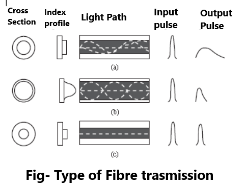
There are three basic types of light guides that are usually identified according to fiber design:
(a) Multimode, stepped refractive index profile
(b) Multimode, graded index
(c) Single mode, stepped index
The basic differences in the three modes are illustrated in Figure. Multimode, stepped refractive index profile fibers, (a) in Figure, are often used for image transmission and short-distance data transmission. The number of rays or modes of light that can be guided by this type of fiber depend on the core size and on the difference in refractive index between the core and the cladding. A transmitted pulse flattens out as it travels down the fiber because the higher angle modes have a greater distance to travel than the low angle modes. This limits the data transmission rate and the distance because it determines how close the pulses can be spaced without creating overlap at the receiving end.
In the graded index multimode fiber, (b) in Figure, the refractive index decreases with radial distance from the center. This tends to minimize pulse broadening due to the mode dispersion since the light rays travel more slowly near the center of the fiber. This type of fiber is used for medium-distance, intermediate rate transmission.
High rate transmission systems use the single mode fiber, (c) in Figure. These fibers have low refractive index difference and a small core size, which tends to eliminate pulse dispersion since only one mode is transmitted. This type of fiber is useful for long-distance, high data rate transmission systems.
The wavelength of light transmitted is a critical parameter in determining the attenuation of the signal. Experience has shown that the lowest attenuation occurs with infrared wavelengths of 850, 1300, and 1500 nm. The 850nm wavelength, commonly used for utility applications, is available from light-emitting diodes (LEDs) or laser diodes (LDs). The use of the longer wavelengths is spreading rapidly, however.
Splicing of fiber cables has proven to be rather easy in spite of the small size of the fibers. Almost lossless splices may be fabricated in the field and have proven to be quite reliable. A number of splicing techniques have been developed, some of which are mechanical while others depend on fusing or welding the glass ends together. Splicing is important since some applications link stations that are many kilometers apart. The physical arrangement employs transmission static wires that incorporate fiber-optic cables in several optional configurations. Testing has also been performed in constructing high-voltage phase conductors that incorporate fiber-optic strands for communications.
Utility applications for fiber-optic data transmission are growing rapidly. The need for data acquisition and communications for supervision, control, and protection are the primary applications. In the past, these needs were met using a variety of communications media, such as microwave, power line carrier, and hard-wired circuits. Optical systems, however, offer an almost ideal replacement for these media due to three major advantages: immunity to high electromagnetic fields, wide bandwidth, and the nonconducting characteristic of the fiber cables.
The fiber systems offer excellent tolerance to vibration, no cross-talk with adjacent cables, immunity to EMI and RFI, no spark or fire hazard, no short-circuit loading, no ringing or echoes, and no contact discontinuity. Moreover, test installations show that the cost is often competitive.
One application that is attractive is interstation communications, control, and protection. Interstation links are typically from a few hundred meters to a few tens of kilometers. Repeater stations are required at regular intervals, but the distance between them is a function of the attenuation and is continually increasing.
Intrastation applications are also being tested with excellent results. Here, the fiber-optic alternative is attractive because of its freedom from interference problems and because of the insulation characteristics of the fiber cables themselves. Signals from transducers and circuit breakers are converted to digital form and transmitted to a control room, where they are fed to microcomputers for processing.
These microcomputers work with low-voltage input signals and would be damaged by transients. Here, the use of fiber cables is an ideal solution, since the cable isolates the sensitive equipment from the high-voltage equipment and shields the transmitted data from any type of outside interference. Applications in generating stations are also growing rapidly, due to the distributed controls now being used in power plants. Here, fiber optics eliminates such problems as ground loops and interference and also requires much less space than the older equipment. Fiber-optic systems are even being placed inside light-water nuclear reactors to gather data on the reactor operating conditions.
The actual measurement of power system parameters is critical to any communications and control system. The measurement of voltage, current, temperature, pressure, and other physical parameters is the heart of any control and protection system. The potential of optical devices as sensors provides important new opportunities.
The ideal sensor for utility applications should have the following characteristics
Nonmagnetic. Impervious to external influence
Passive. Self-powered
Fully dielectric. No need for insulating support structures
Accurate. Capable of precision measurement
Optics-based sensors promise benefits in all of these areas. The development of optical sensors, together with optical data transmission systems, promises to provide new methods of data acquisition and transmission that will eliminate problems that have always been difficult for the protection engineer. Future protection and control systems should have the benefit of cleaner signals, uncorrupted by outside interference. Moreover, the optical concept meshes perfectly with the low-voltage ratings of digital devices that will be the heart of future protective systems.
I do agree with all of the ideas you have presented in your post. They’re very convincing and will definitely work. Still, the posts are too short for novices. Could you please extend them a little from next time? Thanks for the post.