
Table of Contents
ToggleWhat is Optical Current Transducers?
The principle of optical current transducers devices is based on a measurement of the magnetic field in the vicinity of the current-carrying conductor. The measurement is based on optical modulation and demodulation of the Faraday effect. Using this technique, it is possible, in principle, to measure even dc current.
The foregoing discussion indicates that there are problems associated with the accurate acquisition of system currents due to faulted system conditions. This is especially a problem in capturing the transient offset currents that are required to correctly analyze the faulted system conditions. CTs tend to saturate more easily with transiently offset current than current that is symmetrical with respect to zero. A new type of current transducer has been introduced, which solves many of the problems cited for ferromagnetic transducers.
Working Principle of Optical Current Transducers
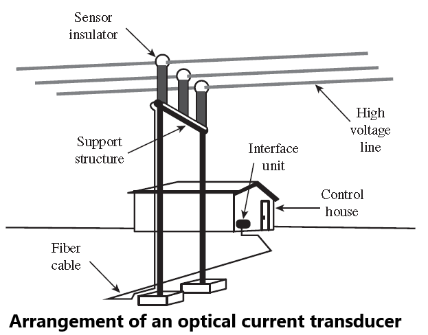
A simplified view of this type of optical current transducer (OCT) implementation is shown in Figure. The principal elements of the system are the sensor assembly, where the field measurements in the vicinity of the conductors are made, the fiber-optic cable that transmits the measured signals, and the signal processing unit, which consists of an optical interface and a computer.
Several devices of this type have been introduced, and others are sure to follow. All proposed systems use fiber optics to isolate the grounded parts from the high-voltage parts of the system, as shown in Figure.
Considerable effort has been concentrated in producing an OCT. These devices are not CTs, but optical electronic measurement systems. There are several different methods that can be used to design an OCT, and most of the methods explored are not based on transformer principles. The power level of the signal available for ground-based processing is weak, being typically in the microwatt range.
This is in contrast to the signal level of ordinary CTs, which is at a level of several watts. The OCT has several advantages over conventional CTs. The OCT is light in weight, being much lighter than an oil-filled CT of similar rating, which results in savings in installation cost. Optical systems are immune from electrical noise.
They provide safety advantages due to the natural insulating quality of the optical transmission fibers. The optical systems are also less likely to fail catastrophically than conventional CTs. Optical current measurements have been investigated since the late 1960s but were not extensively developed until the late 1970s and early 1980s. As a result of extensive research, several different approaches have been explored. Most of the systems under active development employ some technique to measure the magnetic field associated with the current in the conductor of interest. This is an application of Ampere’s law, which can be written as
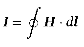
where I is the current, H is the magnetic field intensity, and dl is the closed path of integration. The path of integration is optional and is accomplished in different ways by the developers, using circular, square, or other path configurations. Other methods can be used, but the conversion from magnetic to optical signals is currently the most common. This type of conversion is usually referred to as the “Faraday effect” or the “magneto-optic effect” in the technical literature.
In practice, transparent glasses or crystals are used to construct the Faraday effect devices. These glasses have the property that the value of the refractive index depends on the direction of propagation and the polarization of the light and the refractive index has different values for two mutually orthogonal polarizations of the light wave. The plane of polarization is proportional to the magnetic field in the material and is measured by the rotation of the plane of polarization using various methods.
Types of Optical Current Transducers
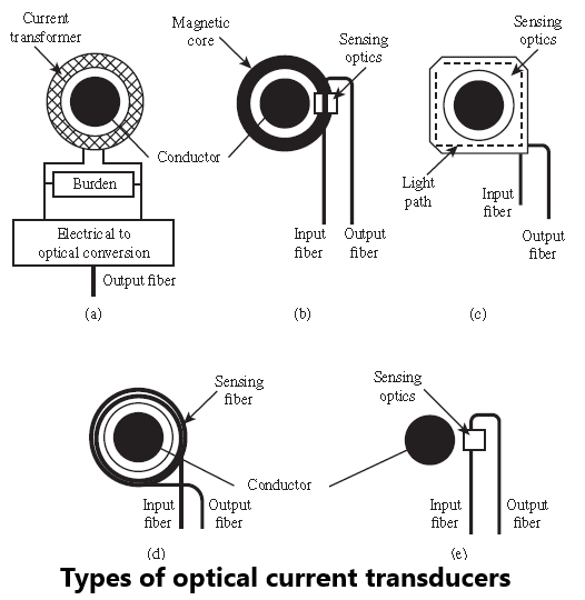
The physical devices that have been developed can be classified into five different types, as shown in Figure.
Type 1 uses an ordinary CT with an added insulated optical transducer added.
Type 2 uses a magnetic circuit around the conductor and measures the field inside the magnetic core optically in an air gap.
Type 3 uses an optical path in a block of optically active material, with the light path enclosing the current in the conductor exactly once, which is an optical implementation of a conventional CT.
Type 4 uses an optical path inside a fiber that is wound around the conductor any number of times.
Type 5 measures the magnetic field at a point near the conductor and is therefore not considered a true current transducer.
The OCT will include a significant amount of electronic equipment, and the impact of a failure in this equipment will need to be considered. A key feature of OCT is the ability to monitor the integrity of the measurement and raise an alarm if the measurement is found to be outside certain tolerances.
This alarm may be configured just to call for maintenance, or to block the protection systems that use the measurement for mitigating a power system problem. The user will need to consider the sensitivity of the alarm and the impact of an incorrect measurement together with the impact of an incorrect protection operation when deciding how to use the alarm.
Advantage of Optical Current Transducers
The signal obtained from the current-carrying conductor is transmitted to electronic processing equipment using fiber-optic cables, which have the advantage of electrical insulation and rejection of electromagnetic induction noise.
The dynamic and frequency range of the optical devices are greatly superior to electromagnetic transformers.
The transducers are compact and lightweight devices.
I would like to thnkx for the efforts you’ve put in writing this blog. I’m hoping the same high-grade blog post from you in the upcoming as well. Actually your creative writing abilities has encouraged me to get my own site now. Really the blogging is spreading its wings fast. Your write up is a good example of it.