
Table of Contents
ToggleDistance Relay Coordination with case study
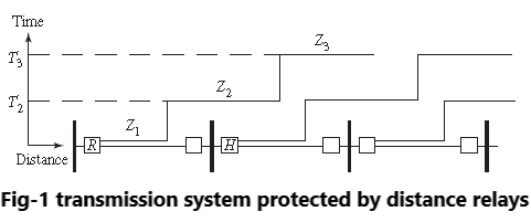
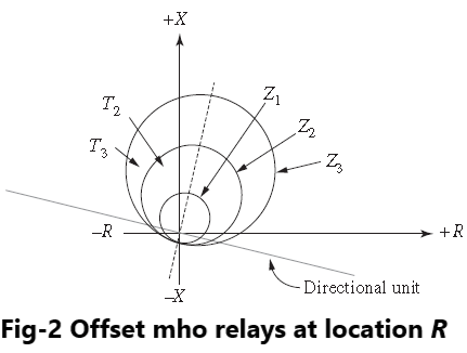
The coordination of distance relays is relatively simple, but there are certain principles that may be stated. Consider a portion of a transmission system shown in Figure-1. We are interested in the relay at R, which is a distance relay that must be coordinated with other distance relays downstream from its position. The relay at R, as well as the downstream relays, are coordinated by having their zone 1 protection operate with no intentional time delay, but with delayed clearing for faults detected in zones 2 and 3. In all cases, the relays are assumed to be directional, or to have directional elements, as shown in Figure-2.
The principles of directional distance relay coordination may be stated as follows.
Zone 1setting
Zone 1 protection is set to trip with no intentional delay. Clearly, this zone must underreach the remote end of the line, since it is not possible to distinguish the exact location of faults near the remote bus. Zone 1 is usually set to reach 85–90% of the total line length for phase relays and about 75–85% for ground relays.
Zone 2 setting
The primary purpose of zone 2 protection is to cover the remote end of the line that is not covered by the zone 1 protection. To do this without error, this zone must reach well beyond the remote bus. This requires a time delay in order to coordinate with the zone 1 protection of the adjacent line relay at H (or other instantaneous protection at H), as noted in Figure-2.
About 0.25 seconds plus the adjacent breaker opening time is usually recommended to assure this coordination. If the remote relay is a time overcurrent relay rather than a distance relay, a longer coordination time setting is recommended. The impedance setting of zone 2 protection should be at least 120% of the protected line impedance. Zone 2 of the relay R protection should not overreach zone 1 of the adjacent downstream relay.
Figure-2 shows a suitable timing arrangement. The coordination of the two line relays must be separated in both the time and impedance coordinates. Sometimes, due to line lengths (short line following long line), it is not possible to set the zone 2 function at 120% of the protected line and still underreach the zone 1 function of the adjacent downstream relay. In that case, the zone 2 function could be set shorter, and dependence placed on the zone 3 function, or the zone 2 function may have additional delay added to its operating time.
Zone 3 setting
The primary purpose of zone 3 protection is to back up the failure of the breaker at H. Should this breaker fail to open for a fault on its protected line, the breaker at R should be caused to open as backup protection. The reach of this zone can be set to a large value and should reach at least through the second downstream line. The time delay for zone 3 protection should be large and may be set at up to one to two seconds.
Occasionally, the zone 3 protection is arranged to look backward rather than forward. This is important for directional comparison relaying, which is discussed in Chapter 12. The system described above assumes a configuration similar to that shown in Figure-1. This is not always the case, since other lines may terminate at the downstream bus, and fault currents will enter through these other lines. This affects the impedance seen by the distance relay at R for faults beyond the next bus.
Faulted system study case
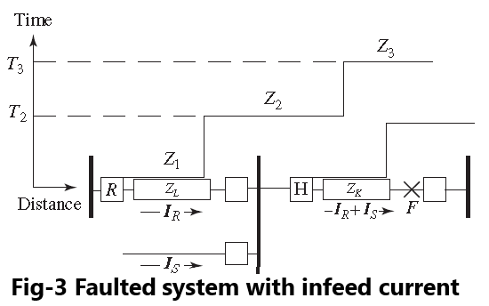
Consider, for example, the network arrangement shown in Figure-3. For the situation depicted in the figure, the relay at R does not see the total fault current and this distorts the total impedance “measured” by the relay at R for faults in the adjacent line. For the case depicted in Figure-3, it can be shown that the impedance seen by the relay at R is given by
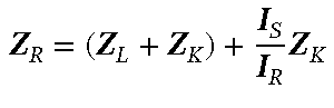
The impedance in parentheses is the actual impedance from the relay to the fault point. The additional impedance that the relay “sees” is due to the infeed current IS and the error is directly proportional to the value of this infeed current. This makes the fault seem farther away than it actually is, reducing the reach of the relay at R for faults beyond relay H. Depending on the amount of infeed, it may help zone 2 of the relay underreach remote zone 1 functions.
As noted above, zone 2 reach must not exceed the zone 1 reach of the relay at H. The reduction of reach of the zone 3 relay at R (due to infeed) for faults beyond the remote terminal impedes its ability to provide backup protection for failure of the breaker at H. If the zone 3 relay reach is increased too much, it may operate undesirably under heavy load conditions.
Reliability regulators may have special rules to ensure transmission line protection devices will not operate under heavy load conditions. Regardless of loading conditions under normal or contingency conditions, “heavy load” will often be considered as the maximum emergency short-time rating of the transmission line. This ensures that the full rated capability of the line is available under stressed system conditions.
Fault analysis studies of the system will provide data to compute the possible error and required setting to back up the remote protection with infeed from other sources. These same studies will identify the apparent impedance presented to the relay under maximum rated line loading conditions. Credible contingencies resulting in reduced infeed at the remote terminal must also be considered when checking whether the increased reaches of zones 2 and 3 will coordinate with remote protections.
Your article helped me a lot, is there any more related content? Thanks!
Thank you for your sharing. I am worried that I lack creative ideas. It is your article that makes me full of hope. Thank you. But, I have a question, can you help me?