
Table of Contents
ToggleTypes of synchronous motor starters
Manual push button synchronising starter
Timed semi-automatic synchronising
Automatic starter using polarised field frequency relay
Manual push button synchronising starter
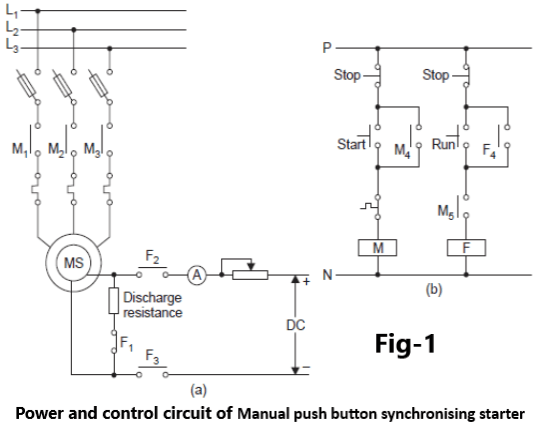
When the START push button shown in Fig-1. is pressed contactor M gets energised and the motor starts as induction motor.
The field winding remains shorted through normally closed contact F 1 and discharge resistance.
When the motor has reached its maximum speed, the RUN push button is closed which energises and holds contactor F contacts F 2 and F 3 closed and contact F 1open.
The field winding is thus energised and the motor pulls into synchronism.
An ammeter and a rheostat are connected in the field circuit to control the excitation current.
Unity power factor of the motor can be obtained by adjusting the rheostat A leading power factor can also be obtained by increasing the excitation The disadvantage of the starter is that synchronisation of the motor depends entirely upon the judgement of the operator.
Timed semi-automatic synchronizing
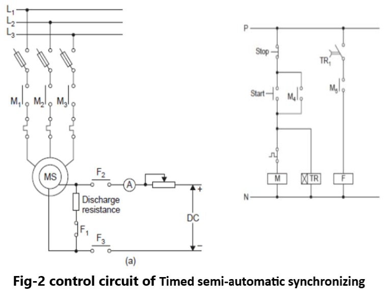
In this method the synchronous motor may be brought up to synchronous speed by exciting the field winding with the help of a Definite Time relay instead of a push button The control scheme is as shown inFig-2.
In this circuit, timer TR is energised along with the main contactor.
After a pre set time delay the rotor accelerates to its maximum when the contact TR 1 closes and further accelerates the rotor to synchronous speed by energising the field winding.
The setting of the timer is adjusted to the maximum value ever required for the motor to accelerate This method of starting, like the push button operated synchronising method, is also not satisfactory because of the reason that if the synchronism operation fails, it becomes necessary to depress the STOP button and repeat the starting cycle Rotor will however continue to rotate and only the timing cycle will start again.
It thus follows that neither the push button nor the timer method of synchronising is a satisfactory method of starting.
Automatic starter using polarised field frequency relay
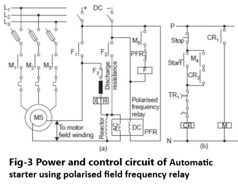
It is known that synchronous motor is started by first accelerating the rotor with the help of its squirrel cage winding up to near its synchronous speed and then synchronising by applying the dc field excitation.
In an automatic starter using polarised field frequency relay, synchronization is obtained automatically when about 92 to 97 percent synchronous speed is obtained with the help of a Polarised Field Frequency Relay (PFR).
Such a PFR has two coils one for ac supply and the other for dc supply.
This relay is used in the circuit along with a reactor as shown in Fig-3 The working principle of a PFR will be discussed a little later.
First we will discuss the functions of a PFR relay and an Out of Step Relay, TR used in the starter circuit shown in Fig-3.
When the START push button is pressed, CR relay gets energised and consequently the main contactor M is energised through its contact CR 1 It gets hold through its contact CR 2 and contact M4 of the main contactor.
Normally closed ( contact of the overload relay and the Out of Step Relay TR are connected in serieswith AC coil of relay CR.
At the instant of starting when contactor M closes and the motor starts on its squirrel cage winding, the polarised field frequency relay ( opens its normally closed contact PFR 1 and thus does not allow the field contactor F to get energized.
When the motor reaches 92 to 97 percent of its synchronous speed, PFR relay closes its contact PFR 1which causes energization of the field contactor F through already closed contact M 5.
A positive interlocking between the normally closed and the normally open contacts of contactor F causes the normally open contacts F 1 and F 2 to close earlier than the opening of the normally closed contact F 3.
This positive overlap is desired in contactor F so that the field winding does not remain open at any instant during starting or running of the motor An open field winding can cause damage of insulation of the winding due to high voltage developed in it.
From the circuit diagram it is clear that as long as contactor F is de energised the field winding remains shorted through the normally closed contact F 3 the discharge resistance, the Out of Step Relay TR and the reactor.
Now let us consider the instant when the contactor F closes The closing of field contactor F applies dc excitation to the field winding and causes the motor to pull into synchronism.
Now let us consider the function of Out of Step Relay TR which is connected in series with the field discharge circuit It the motor fails to synchronise or re synchronise after pulling out of synchronism
within the pre set time delay of TR relay and if the amount of current induced in field winding exceeds the value set on TR relay, the relay contact opens thereby de energising the main contactor of the motor.
Pingback: Jogging operation of Motor - Electricalsphere