
Identifying Motors
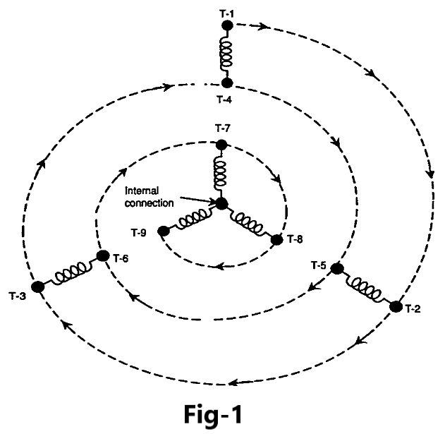
Electric motors with no identification (no name plate or lead tags) must often be maintained and repaired. Follow these steps to determine an unknown motor’s characteristics, based on the NEMA Standard method of motor identification. First, sketch the coils to forma wye. Identify one outside coil end with the number one (1), and then draw a decreasing spiral and number each coil end in sequence as shown in Figure-1.Using a DMM, ohmmeter, or continuity tester, the individual circuits can then be identified as follows:
Step 1. Connect one probe of the tester to any lead, and check for continuity to each of the other eight leads. A reading from only one other lead indicates one of the two-wire circuits. A reading to two other leads indicates the three-wire circuit that makes up the internal wye connection.
Step 2. Continue checking and isolating leads until all four circuits have been located.
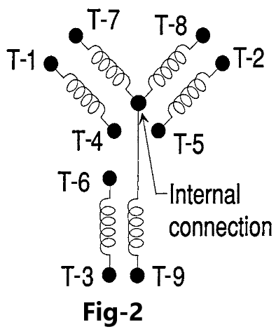
Tag the wires of the three lead circuits T-7, T-8,and T-9 in any order. The other leads should be temporarily marked T-1 and T-4 for one circuit,T-2 and T-5 for the second circuit, and T-3 andT-6 for the third and final circuit. The following test voltages are for the most common dual-voltage range of 230/460 V. For other motor ranges, the voltages listed should be changed in proportion to the motor rating. As all the coils are physically mounted in slots on the same motor frame, the coils will act almost like the primary and secondary coils of a transformer. Figure-2 shows a simplified electrical arrangement of the coils. Depending on which coil group power is applied to, the resulting voltage readings will be additive, subtractive, balanced, or unbalanced depending on physical location with regard to the coils themselves.
Step 3. The motor may be started on 230 V by connecting leads T-7, T-8, and T-9 to the three-phase source. If the motor is too large to be connected directly to the line, the voltage should be reduced by using a reduced voltage starter or other suitable means.
Step 4. Start the motor with no load connected and bring up to normal speed.
Step 5. With the motor running, a voltage will be induced in each of the open two-wire circuits that were tagged T-1and T-4, T-2 and T-5, and T-3 and T-6. With a voltmeter, check the voltage reading of each circuit. The voltage should be approximately 125 to 130 V and should be the same on each circuit.
Step 6. With the motor still running, carefully connect the lead that was temporarily marked T-4 with the T-7 and line lead. Read the voltage between T-1 and T-8 and also between T-1 and T-9. If both readings are of the same value and are approximately 330 to 340 V, leads T-1 and T-4 may be disconnected and permanently marked T-1 and T-4.
Step 7. If the two voltage readings are of the same value and are approximately 125to 130 V, disconnect and interchange leads. If the test calls for equal voltages of 125 to130 V and the reading is only80 to 90 V, this is acceptable as long as the voltage readings are nearly equal. T-1 and T-4 and mark permanently (originalT-1 changed to T-4 and original T-4changed to T-1).
Step 8. If readings between T-1 and T-8 and between T-1 and T-9 are of unequal values, disconnect T-4 from T-7 andreconnectT-4 to the junction of T-8 and line.
Step 9. Measure the voltage now between T-1and T-7 and also between T-1 and T-9. If the voltages are equal and approximately330 to 340 V, tag T-1 is permanently marked T-2 and T-4 is markedT-5 and disconnected. If the readings taken are equal but are approximately125 to 130 V, leads T-1 and T-4 are disconnected, interchanged, and markedT-2 and T-5 (T-1 changed to T-5, and T-4 changed to T-2). If both voltage readings are different, T-4 lead is disconnected from T-8 and moved to T-9. Voltage readings are taken again(between T-1 and T-7 and T-1 and T-8)and the leads permanently marked T-3and T-6 when equal readings of approximately330 to 340 V are obtained.
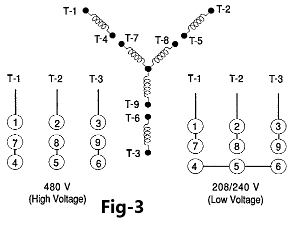
Step 10. Follow the same procedure for the other two circuits that were temporarily marked T-2 and T-5 and T-3 and T-6,until a position is found where both voltage readings are equal and approximately330 to 340 V and the tags change to correspond to the standard lead markings as shown in Figure-3.
Step 11. Once all leads have been properly and permanently tagged, leads T-4, T-5, andT-6 are connected together and voltage readings are taken between T-1, T-2,and T-3. The voltages should be equal and approximately 230 V.
Step 12. As an additional check, the motor is shut down and leads T-7, T-8, and T-9are disconnected, and leads T-1, T-2,and T-3 are connected to the line.
Connect T-1 to the line lead T-7 was connected to, T-2 to the same line as T-8 was previously connected to, and T-3 to the same lead that T-9 was connected to. With T-4, T-5, andT-6 still connected together to form a wye connection, the motor can again be started without a load. If all lead markings are correct, the motor rotation with leads T-1, T-2, andT-3 connected will be the same as when T-7, T-8, and T-9 were connected.
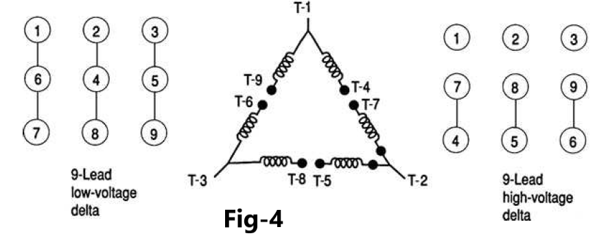
The motor is now ready for service and is connected in series for high voltage or parallel for low as indicated by the NEMA Standard connections shown in Figure-4.
Slot tại SLOT365 có biểu tượng “hot/cold” – cho biết game đang trong chu kỳ trúng hay chưa. TONY06-16
Bạn có thể đặt giới hạn cược/ngày tại xn88 – chơi có trách nhiệm, vui vẻ lâu dài. TONY06-16