
The direction of rotation of dc motor can be reversed in either of the two ways:
- Reversing current through the armature and the interpole windings (if they exist)
- Reversing current through the field windings i.e., through shunt and or series windings but not through the interpole windings (if they exist)
Reversing current through the armature is preferred because reversing current through the field windings involves breaking and making highly inductive current of the field windings.
Reversal of direction of rotation of a dc motor by armature current reversal
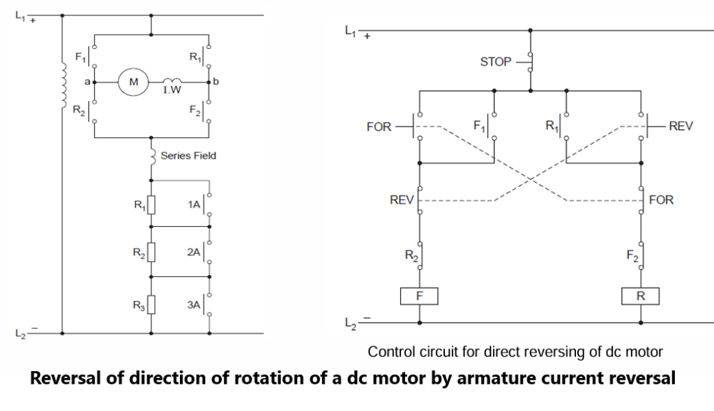
In this circuit when forward contactor contacts F1 and F2 close, current through the armature flows from a to b and the motor rotates in forward direction.
When the motor is to be rotated in reverse direction, forward contactor should get de-energised while the reverse contactor should get energised so that contact R1 and R2 close and thereby current through the armature windings flow in the reverse direction i.e., from b to a.
In both the above cases, however, current through the series field winding flows in the same direction. The forward and reverse contactor should not get energised simultaneously when the motor is running normally with all the armature resistance out of circuit, as it will cause dead short circuit of power lines and also of the counter emf generated in the armature winding.
One method of avoiding this undesired possibility is to interlock both the contactors mechanically. However, more frequently electrical interlocks are provided in the control circuit thereby making it impossible for one contactor to pick up while the other is energized.
For double safety sometimes both mechanical and electrical interlocking of contactors is done. A control circuit for direct reversing of dc motor has been shown in Fig.
Forward and Reverse-push buttons are shown to have back and front contacts.
When the Forward-push button is pressed supply to forward contactor coil reaches through back contact of Reverse-push button and normally close (NC) contact of contactor R. If the motor is to be directly reversed, the Reverse-push button is pressed, its back contact opens and de-energises contactor F. De-energisation of contactor F leads to closing of contact F2 in the coil circuit of contactor R. Contactor R thus gets energised through front contact of REV push button and back contact of FOR-push button and normally closed (NC) contact F2. If the motor is to be brought to rest the STOP-bush button has to be pressed.
Control circuit for forward-stop-reverse operation of a dc motor using OFF-delay timer
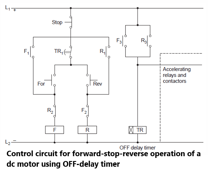
In some applications it may be necessary to stop the motor first before it can be run in the reverse direction. This can be accomplished by using a timer relay and zero speed plugging switches. Here, control circuit using an OFF-delay timer for this purpose has been discussed.
The control diagram has been shown in Fig.
When FOR-push button is pressed contactor F gets energised and the motor runs in the forward direction. Its contact F3 energizes the OFF-delay timer TR which opens its contact TR1 immediately.
At the same time contact F3 also energises the accelerating relays and timers which cut off acceleration resistors from the armature circuit of the motor (refer Fig).
Opening of contact TR1 makes both FOR and REV-push buttons inoperative thus making it impossible to change the direction of rotation of the motor. When the motor direction is to be reversed, first the STOP- push button is pressed, which de-energises contactor F.
Timer TR is also de-energised due to opening of contact F3. After pre-set delay from de energisation of timer TR its contact TR1 will close. This implies that REV-bush button becomes operative only after a pre-set delay from the instant of pressing the STOP-button.
Thus forward to reverse operation becomes possible only when the motor comes to stop first.