Table of Contents
ToggleWhat is Ground or Earth wire?
The ground wire is a conductor running parallel to the power conductors of the transmission line and is placed at the top of the tower structure supporting the power conductors (Fig.(a) ).
For horizontal configuration of the power line conductors, there are two ground wires to provide effective shielding to power conductors from direct lightning stroke whereas in vertical configuration there is one ground wire. The ground wire is made of galvanized steel wire or in the modern high voltage transmission lines ACSR conductor of the same size as the power conductor is used. The material and size of the conductor are more from mechanical consideration rather than electrical. A reduction in the effective ground resistance can be achieved by other relatively simpler and cheaper means
Why Ground or Earth wire used in Transmission line?
The ground wire serves the following purposes:
It shields the power conductors from direct lightning strokes.
Whenever a lightning stroke falls on the tower, the ground wires on both sides of the tower provide parallel paths for the stroke, thereby the effective impedance (surge impedance) is reduced and the tower top potential is relatively less.
There is electric and magnetic coupling between the ground wire and the power conductors, thereby the changes of insulation failure are reduced.
Installation of Ground or Earth wire
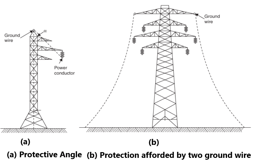
Protective angle of the ground wire is defined as the angle between the vertical line passing through the ground wire and the line passing through the outermost power conductor (Fig. (a)) and the protective zone is the zone which is a cone with apex at the location of the ground wire and surface generated by line passing through the outermost conductor.
According to Lacey, a ground wire provides adequate shielding to any power conductor that lies below a quarter circle drawn with its centre at the height of ground wire and with its radius equal to the height of the ground wire above the ground. If two or more ground wires are used, the protective zone between the two adjacent wires can be taken as a semicircle having as its diameter a line connecting the two ground wires (Fig. (b)). The field experience along with laboratory investigation has proved that the protective angle should be almost 30° on plain areas whereas the angle decreases on hilly areas by an amount equal to the slope of the hill.
The voltage to which a transmission tower is raised when a lightning strikes the tower, is independent of the operating voltage of the system and hence the design of transmission line against lightning for a desired performance is independent of the operating voltage. The basic requirement for the design of a line based on direct stroke are:
- The ground wires used for shielding the line should be mechanically strong and should be so located that they provide sufficient shield.
- There should be sufficient clearance between the power conductors themselves and between the power conductors and the ground or the tower structure for a particular operating voltage.
- The tower footing resistance should be as low as can be justified economically
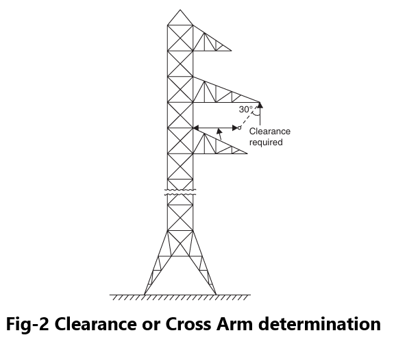
To meet the first point the ground wire as is said earlier is made of galvanized steel wire or ACSR wire and the protective angle decides the location of the ground wire for effective shielding. The second factor, i.e., adequate clearance between conductor and tower structure is obtained by designing a suitable length of cross arm such that when a string is given a swing of 30° towards the tower structure the air gap between the power conductor and tower structure should be good enough to withstand the switching voltage expected on the system, normally four times the line-to-ground voltage (Fig.2)
The clearances between the conductors also should be adjusted by adjusting the sag so that the mid span flashovers are avoided.
The third requirement is to have a low tower footing resistance economically feasible. The standard value of this resistance acceptable is approximately 10 ohms for 66 kV lines and increases with the operating voltage. For 400 kV it is approx. 80 ohms. The tower footing resistance is the value of the footing resistance when measured at 50 Hz.
The line performance with regard to lightning depends upon the impulse value of the resistance which is a function of the soil resistivity, critical breakdown gradient of the soil, length and type of driven grounds or counterpoises and the magnitude of the surge current. If the construction of the tower does not give a suitable value of the footing resistance, following methods are adopted.
One possibility could be the chemical treatment of the soil. This method is not practically possible because of the long length of the lines and because this method needs regular check up about the soil conditions. It is not possible to check up the soil conditions at each and every tower of the line which runs in several miles. Therefore, this method is used more for improving the grounds of the substation.