
Table of Contents
ToggleIntroduction
The protection of shunt capacitor banks requires understanding the basics of capacitor bank design and capacitor unit connections. Shunt capacitors banks are arrangements of series/ paralleled connected units. Capacitor units connected in paralleled make up a group and series connected groups form a single-phase capacitor bank.
As a general rule, the minimum number of units connected in parallel is such that isolation of one capacitor unit in a group should not cause a voltage unbalance sufficient to place more than 110% of rated voltage on the remaining capacitors of the group. Equally, the minimum number of series connected groups is that in which the complete bypass of the group does not subject the others remaining in service to a permanent overvoltage of more than 110%.
The maximum number of capacitor units that may be placed in parallel per group is governed by a different consideration. When a capacitor bank unit fails, other capacitors in the same parallel group contain some amount of charge. This charge will drain off as a high frequency transient current that flows through the failed capacitor unit and its fuse. The fuse holder and the failed capacitor unit should withstand this discharge transient.
The discharge transient from a large number of paralleled capacitors can be severe enough to rupture the failed capacitor unit or the expulsion fuse holder, which may result in damage to adjacent units or cause a major bus fault within the bank. To minimize the probability of failure of the expulsion fuse holder, or rupture of the capacitor case, or both, the standards impose a limit to the total maximum energy stored in a paralleled connected group to 4659 kVar.
In order not to violate this limit, more capacitor groups of a lower voltage rating connected in series with fewer units in parallel per group may be a suitable solution. However, this may reduce the sensitivity of the unbalance detection scheme. Splitting the bank into 2 sections as a double Y may be the preferred solution and may allow for better unbalance detection scheme. Another possibility is the use of current limiting fuses.
The optimum connection for a SCB depends on the best utilization of the available voltage ratings of capacitor units, fusing, and protective relaying. Virtually all substation banks are connected wye. Distribution capacitor banks, however, may be connected wye or delta. Some banks use an H configuration on each of the phases with a current transformer in the connecting branch to detect the unbalance.
Grounded Wye-Connected Banks
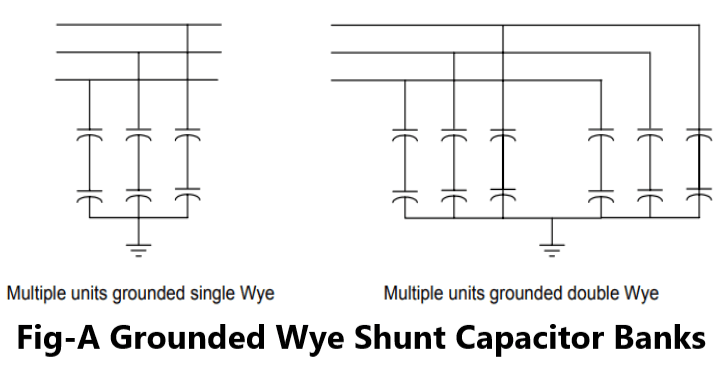
Grounded wye capacitor banks are composed of series and parallel-connected capacitor units per phase and provide a low impedance path to ground. Fig-A shows typical bank arrangements. Advantages of the grounded capacitor banks include:
1.Its low-impedance path to ground provides inherent self-protection for lightning surge currents and give some protection from surge voltages. Banks can be operated without surge arresters taking advantage of the capability of the capacitors to absorb the surge.
2.Offer a low impedance path for high frequency currents and so they can be used as filters in systems with high harmonic content. However, caution shall be taken to avoid resonance between the SCB and the system.
3.Reduced transient recovery voltages for circuit breakers and other switching equipment.
Some drawbacks for grounded wye SCB are:
1.Increased interference on telecom circuits due to harmonic circulation.
2.Circulation of inrush currents and harmonics may cause mis operations and/or over operation on protective relays and fuses.
3.Phase series reactors are required to reduce voltages appearing on the CT secondary due to the effect of high frequency, high amplitude currents.
Multiple Units in Series Phase to Ground – Double Wye
When a capacitor bank becomes too large, making the parallel energy of a series group too great (above 4650 kvar) for the capacitor units or fuses, the bank may be split into two wye sections. The characteristics of the grounded double wye are similar to a grounded single wye bank. The two neutrals should be directly connected with a single connection to ground.
The double Wye design allows a secure and faster unbalance protection with a simple uncompensated relay because any system zero sequence component affects both wyes equally, but a failed capacitor unit will appear as un unbalanced in the neutral. Time coordination may be required to allow a fuse, in or on a failed capacitor unit, to blow. If it is a fuseless design, the time delay may be set short because no fuse coordination is required. If the current through the string exceeds the continuous current capability of the capacitor unit, more strings shall be added in parallel.
Ungrounded Wye-Connected Banks
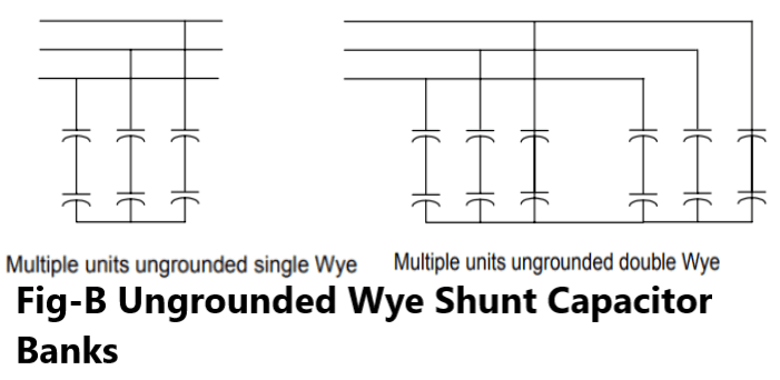
Typical bank arrangements of ungrounded Wye SCB are shown in Fig-B. Ungrounded wye banks do not permit zero sequence currents, third harmonic currents, or large capacitor discharge currents during system ground faults to flow. (Phase-to-phase faults may still occur and will result in large discharge currents). Other advantage is that overvoltages appearing at the CT secondaries are not as high as in the case of grounded banks. However, the neutral should be insulated for full line voltage because it is momentarily at phase potential when the bank is switched or when one capacitor unit fails in a bank configured with a single group of units. For banks above 15kV this may be expensive.
Multiple Units in Series Phase to Neutral – Single Wye
Capacitor units with external fuses, internal fuses, or no fuses (fuseless or unfused design) can be used to make up the bank. For unbalance protection schemes that are sensitive to system voltage unbalance, either the unbalance protection time delay shall be set long enough for the line protections to clears the system ground faults or the capacitor bank may be allowed to trip off for a system ground fault.
Multiple units in series phase to neutral-double wye
When a capacitor bank becomes too large for the maximum 4650 kvar per group the bank may be split into two wye sections. When the two neutrals are ungrounded, the bank has some of the characteristics of the ungrounded single-wye bank. These two neutrals may be tied together through a current transformer or a voltage transformer. As for any ungrounded why bank, the neutral instrument transformers should be insulated from ground for full line-to-ground voltage, as should the phase terminals.
Delta-connected Banks
Delta-connected banks are generally used only at distributions voltages and are configured with a single series group of capacitors rated at line-to-line voltage. With only one series group of units no overvoltage occurs across the remaining capacitor units from the isolation of a faulted capacitor unit. Therefore, unbalance detection is not required for protection.
H Configuration
Some larger banks use an H configuration in each phase with a current transformer connected between the two legs to compare the current down each leg. As long as all capacitors are normal, no current will flow through the current transformer. If a capacitor fuse operates, some current will flow through the current transformer. This bridge connection can be very sensitive. This arrangement is used on large banks with many capacitor units in parallel.
Pingback: Capacitor Bank Unbalance Protection system
Hello! I just would like to give a huge thumbs up for the great info you have here on this post. I will be coming back to your blog for more soon.
I consider something really interesting about your weblog so I saved to my bookmarks.
I?¦ve learn some excellent stuff here. Certainly value bookmarking for revisiting. I wonder how so much effort you place to make any such excellent informative website.
There are certainly a number of details like that to take into consideration. That could be a nice point to carry up. I supply the ideas above as general inspiration however clearly there are questions just like the one you bring up the place an important factor will likely be working in trustworthy good faith. I don?t know if greatest practices have emerged round things like that, however I’m certain that your job is clearly identified as a fair game. Each boys and girls feel the impact of only a moment’s pleasure, for the remainder of their lives.
You are my intake, I have few blogs and very sporadically run out from brand :). “To die for a religion is easier than to live it absolutely.” by Jorge Luis Borges.
I?¦m no longer positive the place you are getting your information, but great topic. I needs to spend a while learning much more or understanding more. Thanks for fantastic information I was looking for this info for my mission.
Pingback: Location of Capacitors for Power Factor Improvement
Only wanna state that this is very beneficial, Thanks for taking your time to write this.