
Unbalance Protection for Ungrounded Single Wye Banks
The simplest method to detect unbalance in single ungrounded Wye capacitor banks is to measure the bank neutral or zero sequence voltage. If the capacitor bank is balanced and the system voltage is balance the neutral voltage will be zero. A change in any phase of the bank will result in a neutral or zero sequence voltage.
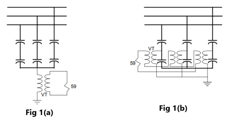
Fig.1(a) shows a method that measures the voltage between capacitor neutral and ground using a VT and an overvoltage relay with 3th harmonic filter. It is simple but suffers in presence of system voltage unbalances and inherent unbalances. The voltage-sensing device is generally a voltage transformer but it could be a capacitive potential device or resistive potential device. The voltage-sensing device should be selected for the lowest voltage ratio attainable, while still being able to withstand transient and continuous overvoltage conditions to obtain the maximum unbalance detection sensitivity. However, a voltage transformer used in this application should be rated for full system voltage because the neutral voltage can under some conditions rise to as high as 2.5 per unit during switching.
An equivalent zero sequence component that eliminate the system unbalances can be derived utilizing three voltage-sensing devices with their high side voltage wye-connected from line to ground, and the secondaries connected in a broken delta. The voltage source VTs can be either at a tap in the capacitor bank or used the VTs of the bank bus.
Figs.1(b) shows a neutral unbalance relay protection scheme for an ungrounded wye capacitor bank, using three phase-to-neutral voltage transformers with their secondaries connected in broken delta to an overvoltage relay. Compared to the scheme in Fig. 1(a), this scheme has the advantage of not being sensitive to system voltage unbalance. Also, the unbalance voltage going to the overvoltage relay is three times the neutral voltage as obtained from Fig 1(a). For the same voltage transformer ratio, there is a gain of three in sensitivity over the single neutral-to-ground voltage transformer scheme. The voltage transformers should be rated for line-to-line voltage.
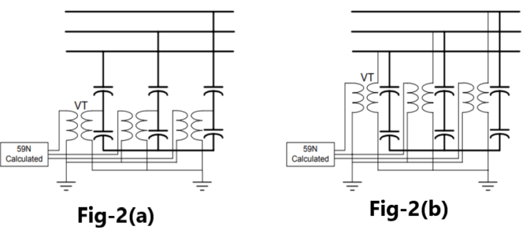
Modern digital relays can calculate the zero sequence voltage from the phase voltages as shown in Fig 2 (a), eliminating the need of additional auxiliary VTs to obtain the zero sequence voltage. Fig 2 (b) shows the same principle but using the VTs on the capacitor bank bus. Although schemes shown in Fig 1(b), 2(a) and 2(b) eliminate system unbalances, they do not eliminate the inherent capacitor unbalance.
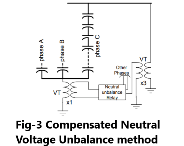
Fig.3 shows a protection scheme that removes the system unbalance and compensate for the inherent capacitor unbalance. It is a variation of the voltage differential scheme for grounded banks described in below section . The best method to eliminate the system unbalance is to split the bank in two Wyes; however, it may not be always possible or desirable. The system unbalance appears as a zero sequence voltage both at the bank terminal and at the bank neutral. The bank terminal zero sequence component is derived from 3 line VTs with their high side Wye connected and their secondaries connected in broken delta.
The difference voltage between the neutral unbalance signal due to system unbalance and the calculated zero sequence from the terminal VTs will be compensated for all conditions of system unbalance. The remaining error appearing at the neutral due to manufacturers capacitor tolerance is then compensated for by means of a phase shifter.
Unbalance Protection for Ungrounded Double Wye Banks
Ungrounded banks can be split into two equal banks. This bank configuration inherently compensates for system voltage unbalances; however, the effects of manufacturers capacitor tolerance will affect relay operation unless steps are taken to compensate for this error.
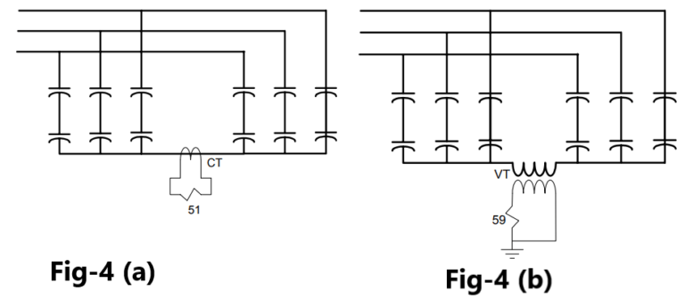
Three methods of providing unbalance protection for double wye ungrounded banks are presented. Fig. 4(a) uses a current transformer on the connection of the two neutrals and an overcurrent relay (or a shunt and a voltage relay). Fig. 4(b) uses a voltage transformer connected between the two neutrals and an overvoltage relay.
The effect of system voltage unbalances are avoided by both schemes, and both are unaffected by third harmonic currents or voltages when balanced. The current transformer or voltage transformer should be rated for system voltage. The neutral current is one-half of that of a single grounded bank of the same size.
However, the current transformer ratio and relay rating may be selected for the desired sensitivity because they are not subjected to switching surge currents or single-phase currents as they are in the grounded neutral scheme. Although a low-ratio voltage transformer would be desirable, a voltage transformer rated for system voltage is required for the ungrounded neutral. Therefore, a high turns ratio should be accepted.
But wanna remark on few general things, The website design and style is perfect, the content material is very great : D.
It’s arduous to seek out educated people on this matter, but you sound like you already know what you’re speaking about! Thanks
Your place is valueble for me. Thanks!…
hi,
thanks for appreciation. Now, my focus on spread my website content to more readers.
To boost my moral, Please share my website to your friends and subscribe my Insta/Telegram/Whatsapp group.
I see something really special in this internet site.
Great perspective
Well structured