
Table of Contents
ToggleWhat is D.C. motor?
A machine that converts d.c. power into mechanical power is known as a D.C. motor. Its operation is based on the principle that when a current carrying conductor is placed in a magnetic field, the conductor experiences a mechanical force. The direction of this force is given by Fleming’s left hand rule and magnitude is given by;
F = BIl newtons
Basically, there is no constructional difference between a d.c. motor and a d.c. generator. The same d.c. machine can be run as a generator or motor.
D.C. motors are seldom used in ordinary applications because all electric supply companies furnish alternating current However, for special applications such as in steel mills, mines and electric trains, it is advantageous to convert alternating current into direct current in order to use d.c. motors.
The reason is that speed/torque characteristics of d.c. motors are much more superior to that of a.c. motors. Therefore, it is not surprising to note that for industrial drives, d.c. motors are as popular as 3-phase induction motors. Like d.c. generators, d.c. motors are also of three types viz., series-wound, shunt-wound and compound wound. The use of a particular motor depends upon the mechanical load it has to drive.
D.C. Motor Working
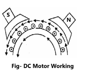
Consider a part of a multipolar d.c. motor as shown in Fig. When the terminals of the motor are connected to an external source of d.c. supply:
(i) the field magnets are excited developing alternate N and S poles;
(ii) the armature conductors carry currents. All conductors under N-pole carry currents in one direction while all the conductors under S-pole carry currents in the opposite direction.
Suppose the conductors under N-pole carry currents into the plane of the paper and those under S-pole carry currents out of the plane of the paper as shown in Fig. Since each armature conductor is carrying current and is placed in the magnetic field, mechanical force acts on it.
Referring to Fig and applying Fleming’s left hand rule, it is clear that force on each conductor is tending to rotate the armature in anticlockwise direction. All these forces add together to produce a driving torque which sets the armature rotating.
When the conductor moves from one side of a brush to the other, the current in that conductor is reversed and at the same time it comes under the influence of next pole which is of opposite polarity. Consequently, the direction of force on the conductor remains the same.
Types of D.C. Motors
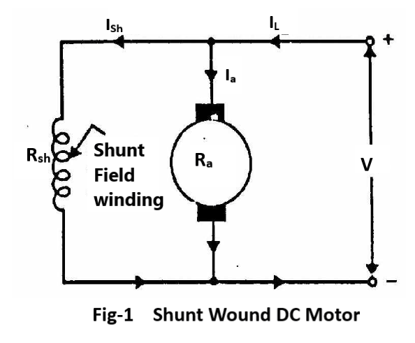
Shunt-wound motor
In which the field winding is connected in parallel with the armature [Fig.1]. The current through the shunt field winding is not the same as the armature current. Shunt field windings are designed to produce the necessary m.m.f. by means of a relatively large number of turns of wire having high resistance. Therefore, shunt field current is relatively small compared with the armature current.
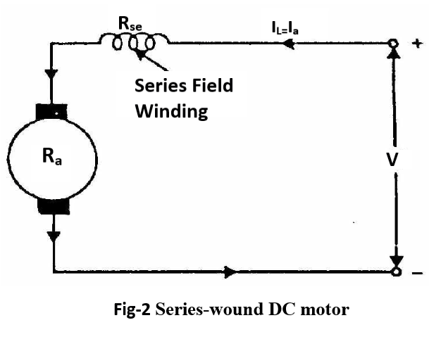
Series-wound motor
In which the field winding is connected in series with the armature [Fig.2]. Therefore, series field winding carries the armature current. Since the current passing through a series field winding is the same as the armature current, series field windings must be designed with much fewer turns than shunt field windings for the same m.m.f. Therefore, a series field winding has a relatively small number of turns of thick wire and, therefore, will possess a low resistance.

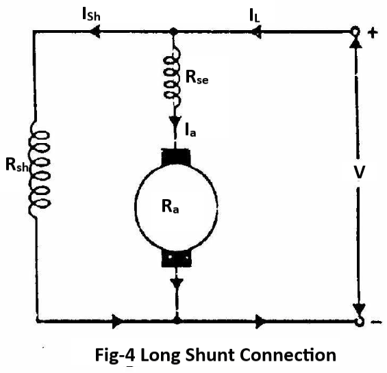
Compound-wound motor
which has two field windings; one connected in parallel with the armature and the other in series with it. There are two types of compound motor connections (like generators). When the shunt field winding is directly connected across the armature terminals [Fig.3], it is called short-shunt connection. When the shunt winding is so connected that it shunts the series combination of armature and series field[Fig.4], it is called long-shunt connection.
The compound machines (generators or motors) are always designed so that the flux produced by shunt field winding is considerably larger than the flux produced by the series field winding. Therefore, shunt field in compound machines is the basic dominant factor in the production of the magnetic field in the machine.
Applications of D.C. Motors
Shunt motors
The characteristics of a shunt motor reveal that it is an approximately constant speed motor. It is, therefore, used
(i) where the speed is required to remain almost constant from no-load to full-load
(ii) where the load has 10 be driven at a number of speeds and any one of which is required to remain nearly constant
Industrial use: Lathes, drills, boring mills, shapers, spinning and weaving machines etc.
Series motors
It is a variable speed motor i.e., speed is low at high torque and vice-versa. However, at light or no-load, the motor tends to attain dangerously high speed. The motor has a high starting torque. It is, therefore, used
where large starting torque is required e.g., in elevators and electric traction.
where the load is subjected to heavy fluctuations and the speed is automatically required to reduce at high torques and vice-versa.
Industrial use: Electric traction, cranes, elevators, air compressors, vacuum cleaners, hair drier, sewing machines etc.
Compound motors
Differential-compound motors are rarely used because of their poor torque characteristics. However, cumulative-compound motors are used where a fairly constant speed is required with irregular loads or suddenly applied heavy loads.
Industrial use: Presses, shears, reciprocating machines etc.
Fault in D.C. Motors
Failure to start
This may be due to (i) ground fault (ii) open or short-circuit fault (iii) wrong connections (iv) too low supply voltage (v) frozen bearing or (vi) excessive load.
Sparking at brushes
This may be due to (i) troubles in brushes (ii) troubles in commutator(iii) troubles in armature or (iv) excessive load.
(i) Brush troubles may arise due to insufficient contact surface, too short a brush, too little spring tension or wrong brush setting.
(ii) Commutator troubles may be due to dirt on the commutator, high mica, rough surface or eccentricity.
(iii) Armature troubles may be due to an open armature coil. An open armature coil will cause sparking each time the open coil passes the brush. The location of this open coil is noticeable by a burnt line between segments connecting the coil.
Vibrations and pounding noises
These maybe due to (i) worn bearings (ii) loose parts (iii) rotating parts hitting stationary parts (iv) armature unbalanced (v) misalignment of machine (vi) loose coupling etc.
Overheating
The overheating of motor may be due to (i) overloads (ii) sparking at the brushes(iii) short-circuited armature or field coils (iv) too frequent starts or reversals(v) poor ventilation (vi) incorrect voltage.
Pingback: Objective (MCQ) question on DC Motors - Electricalsphere
My brother suggested I might like this web site. He was entirely right. This post actually made my day. You can not imagine just how much time I had spent for this information! Thanks!
Outstanding feature
Informative content