
A radial feeder fed from one end protected by overcurrent relay, fails to maintain uninterrupted supply when circuit breaker near to source trips and disconnects all the consequent substations fed by source.

For example, A per Fig-1 tripping of circuit breaker due to relay R1 at section A, interrupts the power for section B, section C and section D.
Uninterrupted supply at all load point is possible if radial feeder is fed from both ends.
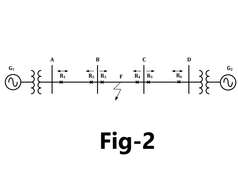
As shown in Fig-2,When fault occurs between section B and section C, relay R3 and R4 trip the circuit breakers of that section only. Section A, B, C and D are uninterrupted and continue to feed the power.
The setting of the relays for such arrangement is carried out on the time-discrimination principle applied to radial feeders.
Relays R1, R3 and R5 are alongside the generator G1
Relays R6, R4 and R2 are alongside the generator G2
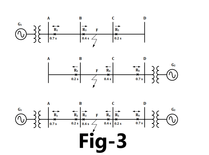
As shown in Fig-3, When fault occurs at F, relays R2 and R5 operates to isolate section B and C, but also misses supply from both end. The remedy of this situation is the integration of directional feature in relay.
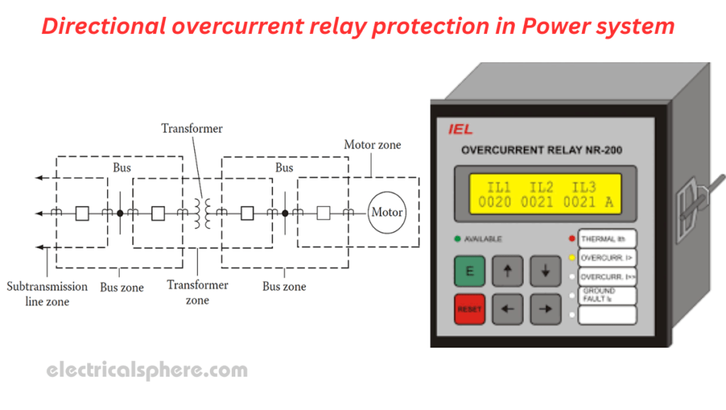
A directional overcurrent protection operates when the current exceeds the pickup value in specified direction.
Fault currents ABF and DCF flow towards the bus for relays R2 and R5 and away from the bus for relays R3 and R4. All these relays are provided with a directional feature whereby they operate only for the direction for which they are meant to operate. The direction of operation is indicated by an arrowhead.
For a fault at F the operation of relays R2 and R5 is restrained because the direction of the fault current is inoperative for both of them while relays R3 and R4 will operate after 0.4 s second isolating the fault.
Relays nearest to the generators R1 and R6, are generally kept non-directional, by indicating double-headed arrows.Directional relays are used for the protection of parallel feeder and ring main system.
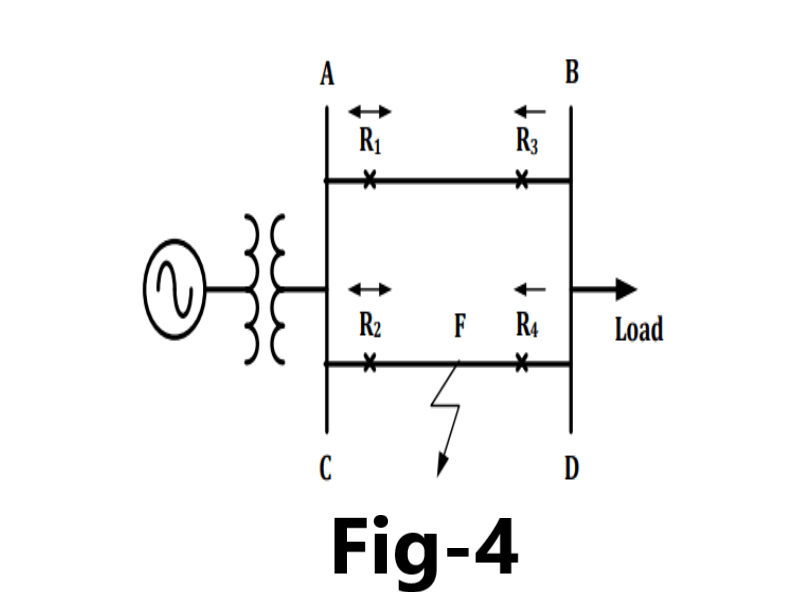
As shown in Fig-4, When fault occurs at F for parallel feeder, relay R2 and R4 of line CD should trip the circuit breaker of that section and full load power must flow via line AB for short duration. If directional feature is not added in relay R3 then relay R3, R4 and R1 trips.
To discriminate the selective operation, relays R3 and R4 are added with directional. The relays R1 and R2 are non-directional overcurrent relays.
Relay R1 is to be graded with the relay R4 such that the former acts as a backup relay to the latter if the latter fails to clear the faults as at F. Similarly, R2 is to be coordinated with R3.

Pingback: Plug setting (PSM) and Time setting multiplier in Overcurrent protection of Transmission line - Electricalsphere
Pingback: Earth fault Relay protection in Power Transmission Line - Electricalsphere
Pingback: Understand Relay and their Logic. What is Numeric relay?
Pingback: Protective Relay testing- Type test on Protective Relay
Pingback: What is Distance Protection Relay
Pingback: Phase Overcurrent setting of Transmission line - Electricalsphere