
Table of Contents
ToggleZone Element Time Delays in Distance relay
The zone 1 elements are usually set with no intentional time delay so that tripping of faults within zone 1 will be as fast as possible.
The time delay of zone 2 and zone 3 elements should be set to coordinate with time-step protection at both the remote and local buses. A typical zone 2 delay setting will be 20–30 cycles. This allows time for the remote zone 1 element to pick up, plus breaker operating time.
Settings for zone 3 residual overcurrent element, if present, depend on the strength of the zero-sequence current source behind the relay. The zone 3 time delay must coordinate with any zone 2 protection which it over reaches. A typical phase distance time delay setting for zone 3 is about 60 cycles.
Figure shows a rough measure of the type of zone reach that is usually considered appropriate. The length of the zone reach arrows in the figure should be interpreted in proportion to the length of the protected line.
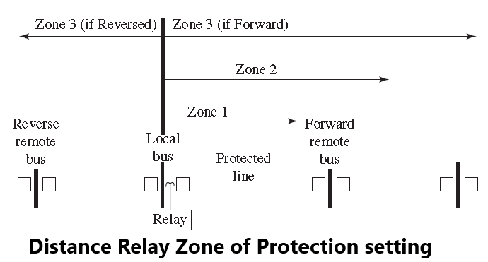
Zone 1 Reach setting
The zone 1 reach is usually set to not overreach the forward line terminal. Zone 1 elements should provide instantaneous protection for three-phase and line-to-line faults inside the zone 1 reach, which is usually set at 80–90% of the line length, independent of communications. The remainder of the line not covered by the zone 1 reach will be protected by zone 2 elements of the relay. It is not practical to extend the zone 1 reach to 100% of the line length due to instrument transformer errors, line data errors, fault study data errors, and small errors in manufacturing tolerance in the relay.
Some engineers choose to set ground distance zone 1 functions to a shorter percentage of the line (say, 5–10% less) than phase distance functions. This is because zero-sequence line impedances are normally not as accurately known as positive sequence line impedances. A number of factors (if not taken into account) can affect the accuracy of the calculation of line zero-sequence impedance.
These factors are primarily mutual coupling, proximity of other conductors (such as gas pipelines, railway lines, and distribution under build), and assumed value of earth resistivity. An important factor with respect to the application and setting of zone 1 functions is whether or not the line is considered “short.” In this case, “short” is not so much related to the physical length of the line, as to the ratio of source impedance to line impedance.
This is known as the source to line impedance ratio, or SIR. The SIR is important, as it affects the voltage at the relay for a fault beyond the remote terminal. The lower the voltage, the more difficult it is for the relay to measure accurately. The voltage between the faulted phases for a fault at the end of the line is important for measuring the impedance to the fault.
Voltage transformers for protection applications are normally specified to meet their accuracy specifications at voltages as low as 5% of rated voltage. Their accuracy is not specified at lower voltages. In addition, as mentioned in Chapter 2, CVTs are known to not necessarily meet their steady-state accuracy specifications during the transient period during the first few tens of milliseconds after a fault.
Since a zone 1 function operates with no intentional delay, the transient performance of a CVT is important for application and setting. Some modern high-speed relays may include special logic for applications with CVTs. This special logic may add a slight delay to zone 1 tripping for faults with very low voltages.
For a given SIR value, the voltage at a line terminal for a fault at the remote terminal will be given By
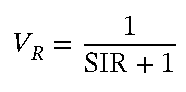
It can be seen that for an SIR of 20, the voltage at the relay during a fault at the remote terminal will be less than 5% of nominal. Some users may choose to reduce the reach of a zone 1 function to less than 80% of the line impedance for SIR>4 and may not apply a zone 1 function at all for very high SIR (greater than 20 or 30). Other users may add a small delay (say, one cycle) to zone 1 tripping for high SIR applications.
Note that when calculating SIR for the purpose of determining zone 1 application and setting, it is important for a fault at the remote terminal to be simulated with the complete network (including the protected line) in service. Having the protected line in service is important because parallel paths will reduce the voltage at line terminal during a fault at the remote terminal. Calculating the source impedance with the protected line out of service will not normally be suitable for a networked system.
Zone 2 Reach setting
Zone 2 elements provide protection for the portion of the protected line beyond the zone 1 reach. Zone 2 elements also serve as backup protection for close-in faults on the forward adjacent lines. In some cases, parallel source infeeds may increase the apparent impedance to the fault from the relay location. Therefore, the zone 2 reach is usually set at 50% of the shortest forward, adjacent line section. Typical settings for lines that are not short will be in the neighborhood of 120–130% of the protected line length. For short lines, the zone 2 element may reach much more than 150% of the line, maybe several multiples of the line impedance.
The critical factor is that they should not reach further than any instantaneous protection protecting equipment beyond the remote terminal. In some cases, with a long protected line followed by a short line beyond the remote terminal, it may not be possible to obtain a dependable zone 2 coverage of the protected line without the risk of overreaching the zone 1 function on the remote short line. In those cases, it may be necessary to either reduce the reach of zone 2 to something less than 120% of the protected line length and depend on the zone 3 function for dependability for faults near the remote terminal. An alternative would be to slow down the tripping time of the zone 2 function so that it coordinates with the delayed protection beyond the reach of the remote zone 1 function.
Zone 3 Reach setting
The instantaneous zone 3 elements are used in several ways in the POTT scheme. These include guarding against current reversal and assisting with weak in feed logic. These schemes require that the zone 3 element reach be reversed and must detect all faults in the reverse direction that are also detected by the zone 2 elements at the remote terminal of the protected line. A time-delayed backup may also be provided by zone 3 elements for faults behind the relay location.
The reverse-looking zone 3 reach setting must be long enough to detect any fault sensed by the overreaching zone 2 element at the remote terminal. Usually, the reach setting is set to match the remote relay zone 2 reach.
In some cases, the zone 3 elements may be set for forward reach. In this case, the zone 3 elements should act as remote backup for faults at remote buses that are two-line sections from the local relay terminal.
Đăng ký tài khoản tại 888slot chỉ mất khoảng 2 phút với các bước đơn giản. Bạn cần cung cấp thông tin cơ bản như email, số điện thoại và thiết lập mật khẩu an toàn. Sau khi đăng ký, hệ thống sẽ gửi mã xác nhận qua SMS hoặc email để hoàn tất quá trình tạo tài khoản. TONY01-06S