
Table of Contents
ToggleDefinition of Earth fault relay
Earth fault relay is used to sense ground or earth-faults i.e. L-G faults and L-L-G faults. The operating principles and constructional features of earth fault relays and phase fault relays are the same i.e. inverse definite minimum time overcurrent (IDMT).
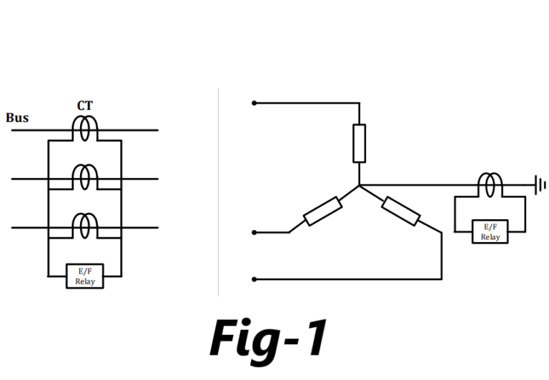
A separate earth fault relay is provided that senses residual current rather than phase current. Under normal conditions the residual current is zero and in case of earth fault, the residual current attains some magnitude. When it exceeds pick-up value, the earth fault relay operates.
Introduction
Earth fault relay pickup with residual current is much below the load current value i.e. 20% – 80% of the rated current in steps of 10%.
In case of earth fault, the value of maximum fault current depends upon the system impedance and the type of neutral earthing. The neutral may be solidly grounded, grounded through resistance or reactance.
As fault impedance for earth faults is much higher than that for phase faults, earth fault current is low compared to the phase fault currents.
When L-G fault occurs near the source, the value of maximum fault current is I=3E/(Z1+Z2+Z3)
and for the radial system with all sequence impedance of the same magnitude, it becomes I=E/Z1 i.e. almost identical to bolted three phase L-L-L-G fault.
A bolted L-G fault current has higher magnitude than L-L-L fault current if value of zerosequence impedance is less than positive sequence impedance.
Moving from source towards the tail end, value of bolted fault current reduces due to increase in total system impedance. Practically zero sequence impedance of feeder is much higher than positive or negative sequence impedance. Hence value of bolted fault current reduces significantly from source to tail end.
Thus, value of bolted three phase fault current is higher than corresponding ground fault current when travelling from source to tail end i.e. it is independent of zero sequence impedance of feeder.
In addition, if L-G fault has an impedance ZF, then the fault current falls even below the bolted L-G fault to a value I=3E/(Z1+Z2+Z0+3ZF)
Hence it observed that value of earth fault current varies significantly depending on fault location and fault impedance. Its value may be even below load current in case of large ground impedance. So over current relays used for phase fault may not be able to detect the earth fault.
A separate earth fault relay is provided that senses zero sequence current rather than phase current. Under normal conditions the zero sequence current is zero and in case of earth fault, the zero sequence current attains some magnitude. When it exceeds pick-up value, the earth fault relay operates.
Transmission line Earth Fault protection
Usually transmission line protection is carried out by
Two overcurrent and one earth fault scheme
Three overcurrent and one earth fault scheme
Two overcurrent and one earth fault scheme
In two over current and one earth fault scheme, all the phase relays carry equivalent value of full load current reflected to CT secondary under normal load condition. Earth relay does not carry any current under normal load condition as well as in case of phase faults i.e. L-L fault and L-L-L faults.
When L-G fault occurs, residual current passes through the earth fault relay coil and operates the earth relay. In case of L-L-G fault, both phase relays and earth fault relay senses the fault and operates.
In case of two over current and one earth relay scheme, when fault occurs over current relay and earth fault relay comes in series connection that increases the burden on CT i.e. CT may saturate.
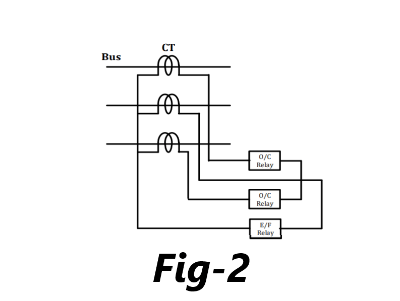
Three overcurrent and one earth fault scheme

For transformer feeder i.e. power transformer between two successive relaying points, two overcurrent and one earth fault scheme does not provide adequate protection.
For example, when L-L fault occurs between y-phase and b-phase of star connected secondary then magnitude of current is IY, 2IY and IY in line R, line Y and line B respectively at delta connected primary.
The magnitude of maximum fault current is 2IY in b-phase where no overcurrent relay is provided in two over current and one earth fault scheme. Hence, tripping of a circuit breaker is delayed because of low fault current in other two phases and y-phase cannot be saved.

Hence one more overcurrent relay in the secondary of y-phase is required i.e. three overcurrent and one earth fault scheme.
Effective Setting of Earth Fault Relays
The primary setting of an overcurrent relay can usually be taken as the relay setting multiplied by the CT ratio. The CT can be assumed to maintain a sufficiently accurate ratio so that, expressed as a percentage of rated current, the primary setting is directly proportional to the relay setting. However, this may not be true for an earth fault relay. The performance varies according to the relay technology used.

Pingback: Understand Relay and their Logic. What is Numeric relay?
Pingback: Different types of Protection on Transmission line
Very Good. Thanks
What about IED’s like (Numerical Relays) having in-built O.C & E.F Protection………Although the fundamental basics remains the very same but IED’s may be little costly and requires good surrounding conditions like better HVAC etc. however Numerical relays more reliable and better in function than the electromechanical ones!!!
Thank You!!!
Pingback: Protective Relay testing- Type test on Protective Relay
Good day,
Please quote your best price and prompt delivery time for the RFQ below.
ITEM QUANTITY
1 RELAY,PROTECTION MANAGEMENT,PN:369 2
2 RELAY,PROTECTION,O/C,E/F,MM:SPAJ 140C 6
3 RELAY,PROTECTION,EARTH FAULT,MM:NERM 5002 20
4 RELAY,PROTECTION,EARTH,ADIT-E, MM:AD-55A 20
5 RELAY,PROTECTION,EL SEC,MM:EL-EIN-1000 20
Best Regards,
CHRISTINE BANDA
+260966110158
Thank you for your sharing. I am worried that I lack creative ideas. It is your article that makes me full of hope. Thank you. But, I have a question, can you help me?