
Solar panel testing is important for take proper output power.For maximum output from solar panel, different types of parameter testing require.Require to measure irradiance of solar energy, DC & AC output, Current output, cell temperature and many more.Here we learn about How to test Solar panel using different meter.
Table of Contents
ToggleTest Solar panel using Digital Pyranometer
A type of actinometer used to measure irradiance of solar energy within the preferred location as well as flux density of solar radiation. The range of solar radiation extends between 300 & 2800 nm.
The SI units of irradiance are W/m² (watts /square meter). Usually, these are used in the fields of researches like climatological & weather monitoring, but current attention is showing interest in pyranometers for solar energy worldwide.
Pyranometer is used to measure the sunlight intensity. It measures irradiance in Watts/m2 .Gives data in digital format. Instantaneous or data-logged / saved measurements.
How to test Solar panel using Digital Multimeter
Digital multimeter measures multiple electrical quantities including voltage current and resistance. Digital multimeter includes prop, clamps, and leads. it is inserted into input of the digital multimeter and connected to the testing device and to take the testing as per the procedure.
Procedure of measure voltage and resistance using Digital Multimeter
1.Select the DC voltage setting in Digital Multimeter.
2.Black probe put in COM slot and red colure probe put in Voltage slot
3.Touch the probe to solar panel
4.Take your solar panel direct into sun and you will get voltage
5.For resistance measurement,select resistance slot in multimeter
Compare your short circuit voltage to nameplate detail and if is near to that than condition of solar panel is good.
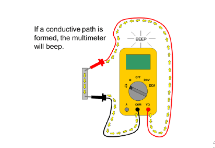
Procedure of Check Continuity test using Digital Multimeter
1.Continuity test is require for check any cell damage or circuit fault occurred or not.
2.Select the Beep sign setting in Digital Multimeter.
3.Black probe put in COM slot and red colure probe put in Voltage slot
4.Touch the probe to solar panel
5.If beep sound hearing then circuit Continuity OK.
Test Solar panel Current using Clamp – On Ammeter
Clamp – On Ammeter is electrical testing tool that integrates with digital multimeter with current sensor. Solar panel current measure using Clamp – On Ammeter.
Avoid testing current of a PV with meter probes – you will pull an arc.

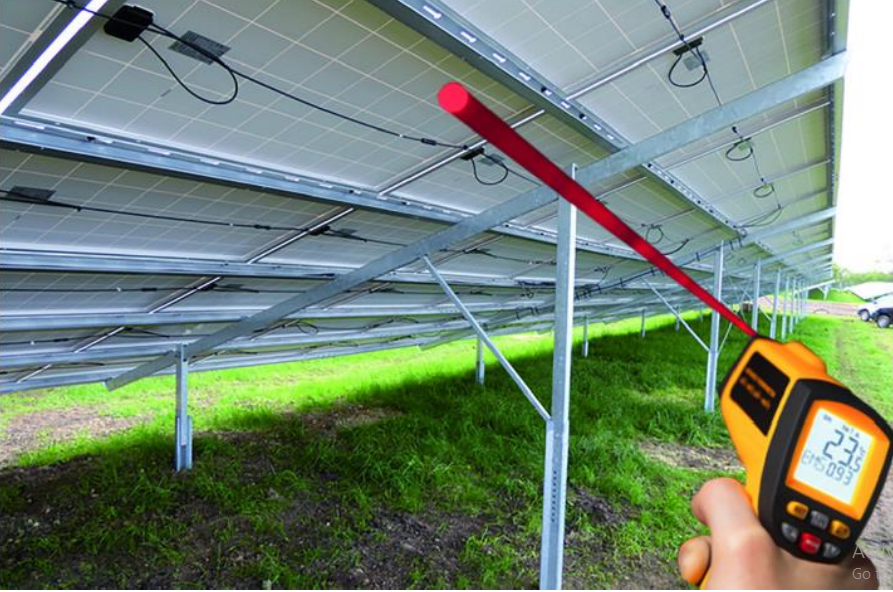
Test solar panel using Infra-Red Temperature Gun
IR temperature gun is used to measure the cell temperature of the PV module. It measures temperature in Celsius and Fahrenheit. Gives data in digital format.
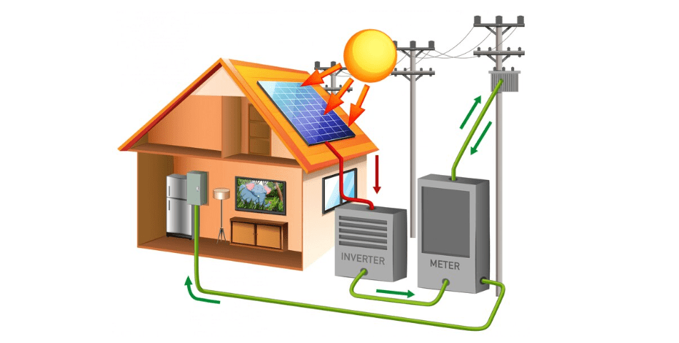
Measuring Solar PV performance
Once your system is installed, make sure it’s operating as designed by measuring its electrical characteristics and the actual power output of the array.
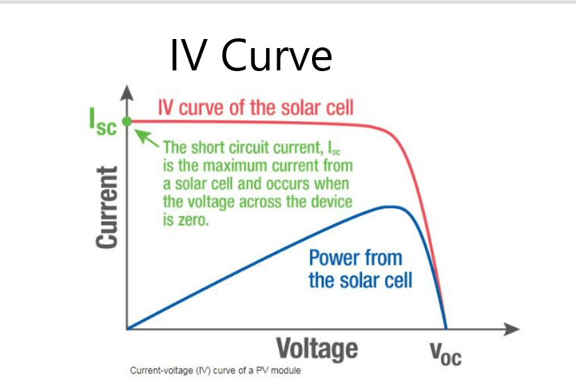
The performance of a PV array is based on its current-voltage (IV) curve. Not only does an inverter convert DC to AC, it maximizes its power output by capturing the current and voltage .since power is voltage x current at which the string is producing the most power.
The short circuit current (Isc) is the maximum current from a cell and no power will be produced because there is no voltage difference: the positive and negative wires are touching. The open circuit voltage (Voc) is the maximum voltage from a cell: no power will be produced because the circuit is open. The point at which the module produces the most power is called the maximum power point (mpp).
To know if an array is working as designed, you need to know the Voc and Isc, which are listed on the module datasheet. Measure the Voc and Isc before and after installation.
Voc is measured by using the digital multimeter to determine the voltage between the positive and negative terminals. Use the Thermometer to determine the temperature of the module to account for the effect of temperature on Voc (the lower the temperature, the higher the voltage and vice versa). Some multimeter provides audio polarity warning while testing Voc.
If it’s reversed, the combiner box or other circuits may be unintentionally connected in series, resulting in voltages over the maximum inverter input voltage.
To test Isc disconnect all parallel circuits and safely short the circuit. Measure the current between the positive and negative terminals through a multimeter. Set the dial to a current greater than expected. Record the values of Isc and Voc and Connect to app and save them for trending and reporting.
Check the insulation resistance of your conductors, the connections between modules and between modules and racking, and your resistance to ground. Use the Earth Ground Clamp to measure earth ground resistance to ensure a resistance of less than 25 ohms.

Pingback: What is Solar Inverter and Types of Solar Inverter - Electricalsphere
Your point of view caught my eye and was very interesting. Thanks. I have a question for you. https://www.binance.com/register?ref=IXBIAFVY