
Table of Contents
ToggleIntroduction
Most Distributed Generators (DGs) are defined as renewable energy, green energy sources and are gradually being utilized to provide a power supply for conventional distribution networks. Distributed generators are made up of induction and synchronous machines. Loss of the power source to the circuit to which an induction generator is connected will normally cause the generator to shut down. The induction generators can not usually become self-excited because they do not have a separate excitation system.
A source of excitation current for magnetizing is required for the stator to induce rotor current. There is no sustained fault current as an induction generator draws its magnetizing current from the network. Thus, they are not capable of supplying isolated loads or sustained fault currents when separated from the power system. The usage of DGs not only gives advantages to electricity users, but it also brings benefits to utilities. The merits of the application of DGs can be summarized as: increased reliability of power supply, improved power quality and voltage stability, loss reduction and high efficiency, environmental concerns and low pollution.
The purpose of protection coordination is to decide the sequence of relay trips and to ensure acceptable coordination grading margins without excessive time delay. DG connections will have a significant influence on the protection coordination. When DGs are connected to the main grid, the protective devices connected will detect different fault current levels and sense the fault current flow in more than one direction.
False tripping of overcurrent relays
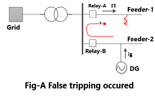
In an active distribution network, both DGs and the external source will be subject to a fault current, whereas in a passive distribution network the fault current flows only from a single resource. Hence, a protective device located in the DG feeder in an active network may see a fault current flow from the DG caused by faults elsewhere in the system. To illustrate this problem in Figure-A, there are two sources supply the network, one is an external grid, another is a distributed generator. The relay A should trip for a short-circuit fault on the adjacent feeder 1; however, the relay B will see the fault current as well and may cause false tripping and then disconnect the non-faulted feeder 2. A solution to this problem, apply directional relays to protect the feeders that may bring about false tripping.
Loss of protective devices grading
The current injected by DGs will change the fault level both in magnitude and direction, which thereby results in a loss of selectivity. The protective devices are designed to sense a certain minimum fault current, which normally includes the ends of the feeder. As the penetration of the DG increases, it is more difficult to detect or sense a fault in overcurrent devices with the settings that were based on the minimum fault current before the DGs was connected. Additionally, the coordination margin is also used to distinguish the operating time of the relays. With more DGs installed out on the feeder, they will cut into the margin. The problem can be resolved by readjusting the settings of the OC relays to build the new grading margin and to acquire the appropriate relay characteristics.
Blinding of overcurrent relays
When a DG is downstream of a relay and upstream of the fault point, the DG will contribute to the total fault current, but it will decrease the fault current seen by the relay at the same time. This may cause delayed tripping of the relay and could, potentially, in the worst scenario lead to the non-tripping of the relay. This problem is referred to as “Blinding of OC protection”.
Effect of infeed on the distance protection
On the basis of the impedance measured, distance relays have the advantage that they can distinguish faults in different parts of a network. Essentially, this involves comparing the fault current, as seen by the relay, against the voltage at the relay location to determine the impedance down the line to the fault. The effect of infeed needs to be taken into account when there are one or more generation sources within the protection zone of a distance relay which can contribute to the fault current without being seen by the distance relay.
Analysing the case presented in Figure-A, it can be seen that the actual impedance to the fault is ZA+ZB, but when the current flows, the impedance appears to the relay as ZA+ZB+(IA/IB)ZB. The impedance seen by the distance relay for a fault beyond busbar B is greater than what actually occurs. This effect is called the “infeed effect”.
The presence of the DG can cause the “infeed effect”. When DGs are added to the distribution network, the fault current from the generation adds to the fault current from the utility.
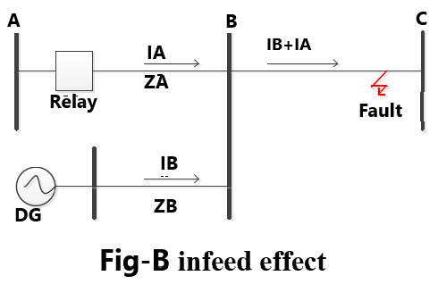
In Figure-B, if the current flows from the DG connected to bus C, the distance relay may not operate according to its defined zone as the relay sees the impedance influenced by the DG as well as the infeed current.
The influence of the DG is the reduction in the reach of the distance relay, which can be summarized in as follows “When a fault occurs downstream of the bus where the DG is connected to the utility, the impedance measured by an upstream relay will be higher than the real fault impedance.”
Conclusion
As a result of the penetration of the DGs in distributed networks, some problems (false tripping, loss of grading, blinding, the effect of infeed) related to protection coordination have arisen. Through a proper design of the protection concept and protection coordination, each of these issues can be solved. Loss of grading margin is an inevitable issue when it comes to protection coordination and necessary readjustment is needed. In terms of overcurrent relays, false tripping and blinding problems could affect the sensitivity and selectivity of the protection system.
The solution is to adopt directional overcurrent relays to prevent the circuit from potential false tripping. As for blinding of overcurrent relay, a combination of IDMT and a definite time characteristics is the solution. The effect of the infeed current could result in under reaching of the protected zone, which should be taken into account when studying the coordination between distance relays.
Your article helped me a lot, is there any more related content? Thanks!