
Table of Contents
ToggleNegative phase sequence protection of induction motor
In case of open circuit fault developed at supply terminal or one pole of circuit breaker does not make contact with supply terminal when induction motor is running, an unbalanced current flows through the motor winding.
Negative sequence component of unbalanced current causes excessive overheating of rotor because rotating magnetic field produced due to the negative phase sequence current rotates at synchronous speed in the opposite direction of rotor i.e. double the supply frequency that produces excessive iron loss in rotor core.
An independent protective sachem is required to protect an induction motor against negative phase sequence.
Definite time over current relay with negative sequence filter is used. CT secondary current is fed to negative sequence filter which provides the AC output voltage proportional to negative phase sequence current of the stator.
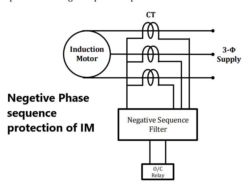
The pick-up of definite time overcurrent relay is normally set at 50% of the starting current of an induction motor with the time delay is of 6 to 10 cycles.
Another practice is to use thermal relay with a characteristics of I2t = K, in which tripping time of thermal relay is inversely proportional to the square of the negative phase sequence current of the stator. Such a relays are provided with 20 – 80% setting range. Negative sequence component of current is filtered from CT secondary current which is fed to thermal relay.
Protection against stalling of induction motor
When a heavy load is thrown on the motor suddenly, the motor stalls i.e. motor does not start and rotor gets blocked. Under the condition of stalling or locked rotor, the speed of the rotor is zero hence motor draws very high currents i.e. 15 to 20 times the rated current.
Sudden increase in current due to stalling, rises mechanical stresses on the parts of rotor and electrical stresses on insulation of winding. Hence, a separate protection against stalling of large induction motor is required.
An instantaneous overcurrent relay operates due to subsequent high stator current and isolate motor from supply.
In certain cases due abrupt heavy overload, the motor does not stop fully but speed falls below the lower steady state speed. If this speed is within safer limit for electrical stress on insulation and mechanical stresses on rotor parts respectively, certain time is required for the motor to gain stable state i.e. safe stalling time, therefore induction motor does not required to trip.
Definite time overcurrent relay with centrifugal speed switch is used as trip coil of the circuit breaker energizes only under the conditions of stalling. When stalling of induction motor occurs, the speed of the motor drops considerably from the normal rated speed, and hence the speed switch will close allowing the circuit breaker to open its contacts.
For gradual overloading, thermal overload relay takes care. In this case tripping of the circuit breaker, due to operation of stalling relay is blocked because of interlock of centrifugal speed switch.
Under voltage protection of induction motor
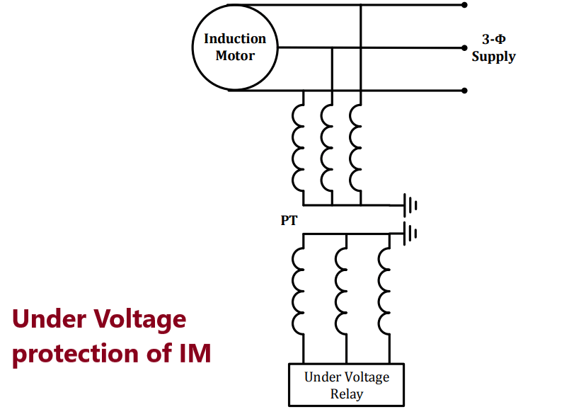
If voltage across motor terminal drops, it draws high current that damages the insulation of motor winding.
Under voltage protection for a group of motors i.e. station auxiliary motors is required because in power stations, the simultaneous starting of a large bank of motors overload the feeding transformer and trips the circuit breaker.
Under voltage relay operates when the voltage across relay coil falls below a predetermined value i.e. typically 85% to 90% of rated voltage.
Under voltage relay coil is energized through potential transformer (PT) secondary. When voltage across the motor terminal falls, PT secondary voltage changes that activates trip circuit.
Pingback: Start and Stall protection of Induction Motor
Hello, I enjoy reading through your article post.
I like to write a little comment to support
you. https://waste-Ndc.pro/community/profile/tressa79906983/
Hello, I enioy reading through your article post. I like to write a little comment to support you. https://waste-Ndc.pro/community/profile/tressa79906983/
Pingback: Overcurrent Protection of Conductor and Machine - Electricalsphere