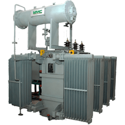
Transformers are critical components in electrical systems, responsible for stepping up or down voltages to facilitate efficient power transmission and distribution. To ensure their safe operation, transformers are equipped with protective devices, including the Oil Temperature Indicator (OTI) and Winding Temperature Indicator (WTI). In this blog post, we understanding OTI and WTI in Transformers and Their Settings.

Table of Contents
ToggleFullform of OTI and WTI
OTI-Oil Temperature Indicator
WTI-Winding Temperature Indicator
What is OTI?
OTI (Oil Temperature Indicator) measure Oil temperature in oil filled transformer. It’ use for protection of transformer. Separate OTI meter placed in transformer.
Working of OTI
The Oil Temperature Indicator (OTI) work on either volumetric expansion of liquid proportional to rise in temperature or bi-metallic principle, and provide indications of top oil temperature via dial type indicators. In all cases, the indicators should be mounted vertically for the most accurate readings.
A sensing bulb, measuring bellow and a small bore capillary connecting the two form the measuring system which is filled with liquid.
When the sensing bulb is exposed to rise in temperature, the liquid inside expands proportionately causing the bellows to expand and drive the linkages for indication and separately, linkages & disc for switch operation.
The bulb/probe should be fitted into the thermometer pocket provided in the transformer main tank cover, near the hottest oil region. Before fitting the bulb/probe, thermometer pockets should be partially filled with transformer oil.
What is WTI?
WTI (Winding Temperature Indicator) measure HV and LV winding temperature. It’s use for protection of transformer. In WTI meter, R,Y,B phase winding temperature indicates.
Working of WTI
Winding Temperature Indicator (WTI) work on either volumetric expansion of liquid proportional to rise in temperature or bi-metallic principle, and provide indications of average winding temperature via dial type indicators. In all cases, the indicators should be mounted vertically for the most accurate readings.
A sensing bulb, measuring bellow and a small bore capillary connecting the two form the measuring system which is filled with liquid.
When the sensing bulb is exposed to rise in temperature, the liquid inside expands proportionately causing the bellows to expand and drive the linkages for indication and separately, linkages & disc for switch operation.
The bulb/probe should be fitted into the thermometer pocket provided in the transformer main tank cover, near the hottest oil region. Before fitting the bulb/probe, thermometer pockets should be partially filled with transformer oil.
WTI is the same as OTI except for the current feed circuit from a CT to a heating element either on the thermometer pocket, or in the instrument itself.
Normally the current feed to WTI is provided from a CT at one phase of the LV winding. Such CT has a suitable ratio to feed the required current to heat the heating element. This additional temperature component from the heating element, together with the prevailing top oil temperature, gives the average winding temperature seen at WTI.
Alarm and Trip Setting of OTI and WTI in Transformer
Oil Temperature Indicator: 85°C for Alarm switch; 95°C for Trip switch
Winding Temperature Indicator: 105°C for Alarm switch; 115°C for Trip switch
It’s setting is different in every Transformer manufacture company.

Cooling Pump and Fan operation setting
Generally, Cooling Pump and Fan operation setting based on WTI of transformer. Cooling Pump and Fan operation setting is different by manufacturing company. We understand by one example,
Case-1: When WTI reached temperature greater than 60 *C, one Group of Pump start. If temperature not control by Pump, WTI reached more than 65 *C, then one group of Fan start. This is same sequence for second group pump and fan.
Case-2:When WTI reached temperature greater than 60 *C, one Group of Fan start. If temperature not control by Fan, WTI reached more than 65 *C, then one group of Pump start. This is same sequence for second group pump and fan.
First start operation of Fan and Pump based on Manufacture company. During erection of transformer, check Pump and Fan operation and verify with manufacture result.


Pingback: Types of Routine Test carried out on Power Transformer
Pingback: Procedure for Maintenance and Periodic Inspection of Transformer - Electricalsphere
Pingback: Interview question of Electrical Power Transformer
Pingback: Preventive maintenance and Check point of Transformer
KINDLY QUOTE THE RATES OF OTI & WTI WITH RS485 PORT FOR 33/11 KV DISTRIBUTION TRANSFORMERS — 03 NOS