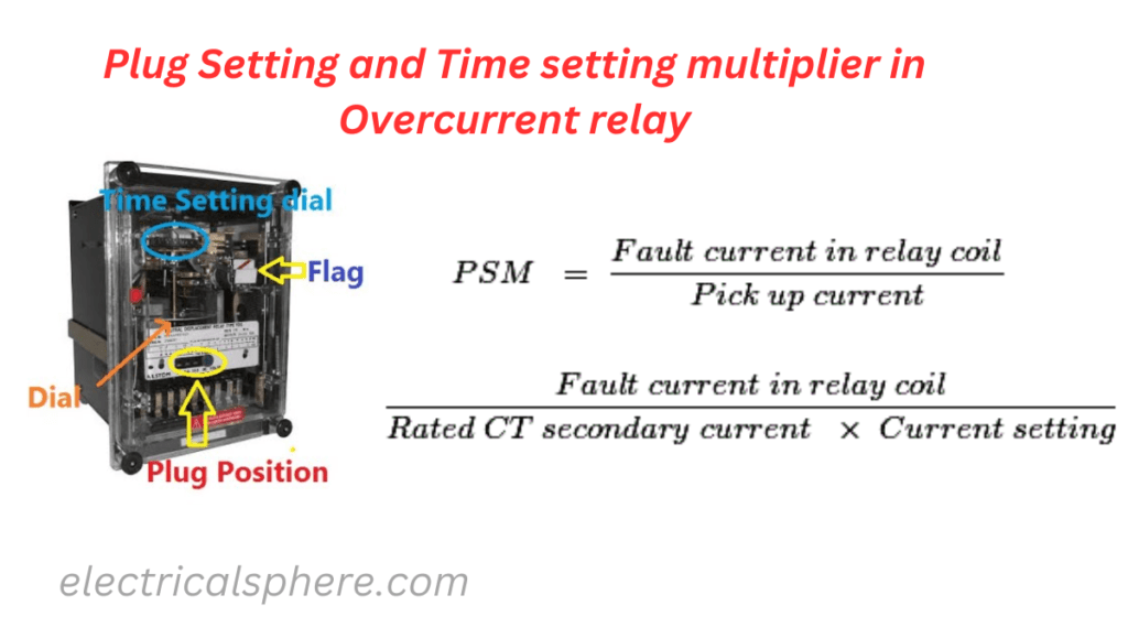
Overcurrent relay operates when load current exceeds pre-set value i.e. pick up value. Transmission lines, distribution lines, large power equipment and industrial systems uses over current protection as it offers cheapest and simplest protection. A wide variety of time-current characteristics are available for overcurrent relays.
Table of Contents
ToggleOver current relay time-current characteristics
Magnetic circuit of an overcurrent relay is designed to saturate above a certain value of the actuating current. Below the value of the actuating current, the relay gives an inverse characteristic and above the saturation value of the current, the relay gives a straight line characteristic i.e. for the value of the current above saturation value the operating time remains constant.
If the core is designed to saturate at
Pick-up value of current, relay gives definite time characteristics
Later stage, relay gives IDMT characteristics
Still later stage, relay gives very inverse characteristics
Very later stage, relay gives very extremely inverse characteristics
Plug Setting Multiplier (PSM)
It is the value of current above which relay operates. For example if relay is set at 1 A, it operates when current exceeds 1 A. A number of tappings are provided on relay current coil that is used to alter number of turns of coil by means of plugs for current setting.
Current setting (plug setting) is either be given in ampere or as percentages of rated current. An over current relay used for line-to-line fault is set at 50% to 200% of rated current in steps of 25% and for earth fault, it is set at 20% to 80% of rated current in steps of 10%.
If relay is set at 75% for line-to-line fault, it operates when current exceeds 0.75 A. If relay is set at 40% for earth fault, it operates when current exceeds 0.4 A.
A time current characteristics is drawn by taking current on x-axis for each plug setting i.e. six curves for line-to-line fault over current relay and seven curves for earth fault relay.
To avoid this complication, actual RMS current flowing in relay coil is expressed as a multiple of the setting current that is known as plug setting multiplier (PSM).
For Example
Relay rating is 1 A and it is set at 200%, i.e. at 2 A. When current flowing through the relay is 100 A, then PSM = 50.Hence, plug setting multiplier is defined as
PSM=CT secondary current/Relay current setting
PSM=Fault Current/(Relay current setting*CT ratio)
For time-current characteristic PSM is taken on the X-axis i.e. only one curve for all the settings of the relay.
Time setting
The operating time of the relay is set at a desired value. In electromechanical type relay, distance travelled by moving contact of the relay for closing the contacts is adjusted to get different operating time i.e. can be set in 10 steps.
The term time multiplier setting (TMS) is used for these steps of time settings and its values are 0.1, 0.2, 0.3, 0.4, 0.5, 0.6, 0.7, 0.8, 0.9 and 1.
For example Suppose that at a particular value of the current or plug setting multiplier (PSM), the operating time is 4 s with TMS = 1. The operating time for the same current with TMS = 0.2 is 4 ´ 0.2 = 0.8 s.

