
Table of Contents
ToggleWhat is Polyphase Transformers?
Almost all the major power generation and distribution systems in the world today are three-phase ac systems. Since three-phase systems play such an important role in modern life, it is necessary to understand how transformers are used in them.
Transformers for three-phase circuits can be constructed in one of two ways. One approach is simply to take three single-phase transformers and connect them in a three-phase bank. An alternative approach is to make a three-phase transformer consisting of three sets of windings wrapped on a common core.
These two possible types of transformer construction are shown in the figures below.

The construction of a single three-phase transformer is the preferred practice today, since it is lighter, smaller, cheaper, and slightly more efficient. The older construction approach was to use three separate transformers. That approach had the advantage that each unit in the bank could be replaced individually in the event of trouble, but that does not outweigh the ad vantages of a combined three phase unit for most applications. However, there are still a great many installations consisting of three single-phase units in service.
Three-Phase(Poly phase) Transformer Connections
A three-phase transformer consists of three transformers, either separate or combined on one core. The primaries and secondaries of any three-phase transformer can be independently connected in either a wye (Y) or a delta (∆ ). This gives a total of four possible connections for a three-phase transformer bank:
Wye-wye(Y-Y)
Wye-delta (Y -∆)
Delta-wye (∆-Y)
Delta-delta (∆-∆)
The key to analyzing any three-phase transformer bank is to look at a single transformer in the bank. Any single transformer in the bank behaves exactly like the single-phase transformers already studied. the impedance, voltage regulation, efficiency, and similar calculations for three-phase transformers are done on a per-phase basis, using exactly the same techniques already developed for single-phase transformers.
The advantages and disadvantages of each type of three-phase transformer connection are explained below along with the relevant connection diagrams.
Wye-wye(Y-Y) Connection

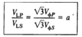
In a Y-Y connection, the primary voltage on each phase of the transformer is given by VØP = VLP / √3. The primary-phase voltage is related to the secondary-phase voltage by the turns ratio of the transformer. The phase voltage on the secondary is then related to the line voltage on the secondary by VLS = √3VØS . Therefore, overall the voltage ratio on the transformer is
The Y-Y connection has two basic problems:
1.If loads on the transformer circuit are unbalanced, then the voltages on the phases of the transformer can become severely unbalanced.
2.Third-harmonic voltages can be large.
If a three-phase set of voltages is applied to a Y – Y transformer, the voltages in any phase will be 1200 apart from the voltages in any other phase. However, the third-harmonic components of each of the three phases will be in phase with each other, since there are three cycles in the third harmonic for each cycle of the fundamental frequency. There are always some third-harmonic components in a transformer because of the nonlinearity of the core, and these components add up.
The result is a very large third-harmonic component of voltage on top of the 50 or 6O-Hz fundamental voltage. This third-harmonic voltage can be larger than the fundamental voltage itself.
Both the unbalance problem and the third-harmonic problem can be solved using one of the two following techniques:
A) Solidly ground the neutrals of the transformers, especially the primary winding’s neutral. This connection permits the additive third-harmonic components to cause a current flow in the neutral instead of building up large voltages. The neutral also provides a return path for any current imbalances in the load.
B) Add a third (tertiary) winding connected in ∆ to the transformer bank. If a third ∆ connected winding is added to the transformer, then the third-harmonic components of voltage in the ∆will add up, causing a circulating current flow within the winding. This suppresses the third-harmonic components of voltage in the same manner as grounding the transformer neutrals.
The ∆ connected tertiary windings need not even be brought out of the transformer case, but they often are used to supply lights and auxiliary power within the substation where it is located. The tertiary windings must be large enough to handle the circulating currents, so they are usually made about one-third the power rating of the two main windings.
One or the other of these correction techniques must be used any time a Y-Y transformer is installed. In practice, very few Y-Y transformers are used, since the same jobs can be done by one of the other types of three-phase transformers.
WYE-DELTA Connection
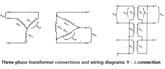
The Y – ∆ connection of three-phase transformers is shown in the figure below. In this connection, the primary line voltage is related to the primary phase voltage by VLP = √3VØP while the secondary line voltage is equal to the secondary phase voltage VLS = VØS . The voltage ratio of each phase is
VØP / VØS = a
So the overall relationship between the line voltage on the primary side of the bank and the line voltage on the secondary side of the bank is:
VLP / VLS = √3VØP / VØS = √3 a
The Y – ∆ connection has no problem with third-harmonic components in its voltages, since they are consumed in a circulating current on the ∆ side. This connection is also more stable with respect to unbalanced loads, since the ∆ partially redistributes any imbalance that occurs.
This arrangement does have one problem, though. Because of the connection, the secondary voltage is shifted 300 relative to the primary voltage of the transformer. The fact that a phase shift has occurred can cause problems in paralleling the secondaries of two transformer banks together. The phase angles of transformer secondaries must be equal if they are to be paralleled, which means that attention must be paid to the direction of the 300 phase shift occurring in each transformer bank to be paralleled together.
DELTA-WYE Connection
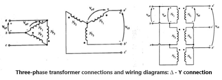
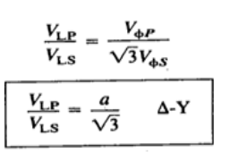
A ∆ – Y connection of three-phase transformers is shown in the figure below. In a ∆ – Y connection, the primary line voltage is equal to the primary-phase voltage VLP = VØP , while the secondary voltages are related by VLS = √3VØS . Therefore, the line-to-line voltage ratio of this transformer connection is given by
This connection has the same advantages and the same phase shift as the Y – ∆ transformer. The connection shown in the figure above makes the secondary voltage lag the primary voltage by 30°, as before.
DELTA-DELTA Connection

In a ∆- ∆ connection, VLP = VØP and VLS = VØS, so the relationship between primary and secondary line voltages is given by:

This transformer has no phase shift associated with it and no problems with unbalanced loads or harmonics.
Pingback: Electrical Substation: Standard Practice and Maintenance Points
I have to thank you for the efforts you’ve put
in penning this blog. I really hope to view the same high-grade blog posts ffom you in the future as well.
In truth, your creative writing abilities has motivated
mme to get my own, personal blog now 😉 https://www.waste-Ndc.pro/community/profile/tressa79906983/
I hve to thank you for the efforts you’ve put in penning ths blog.
I really hope to view the same high-grade blog posts from
you in the future as well. In truth, your creative writing abilities has motivated me to gett my own, personal
blog now 😉 https://www.waste-Ndc.pro/community/profile/tressa79906983/
Pingback: Auto Transformer: Working Principle, Advantage, Application - Electricalsphere
Thanks a bunch for sharing this with all people you actually know what you’re speaking approximately! Bookmarked. Kindly additionally visit my site =). We can have a link trade agreement between us!
Pingback: All day Efficiency of Transformer - Electricalsphere
Quality content