
Table of Contents
ToggleWhat is PLCC (Power Line Carrier Communication)
PLCC is used for tele-communication, tele-monitoring and teleprotection between electric substations through high voltage power lines. This is economic and reliable for inter grid message transfer as well as low bit rate RTU signals.
Power line carrier communication (PLCC) is the technology which is used to communicate between electric EHV substations through existing electrical conductors.
Power line carrier communication (PLCC) techniques
Where long line sections are involved, or if the route involves installation difficulties, the expense of providing physical pilot connections or operational restrictions associated with the route length require that other means of providing signalling facilities are required.
Power Line Carrier Communications (PLCC) is a technique that involves high frequency signal transmission along the overhead power line, typically in the 300Hz to 3400Hz band. It is robust and therefore reliable, constituting a low loss transmission path that is fully controlled by the Utility.
High voltage capacitors are used, along with drainage coils, for the purpose of injecting the signal to and extracting it from the line. Injection can be carried out by impressing the carrier signal voltage between one conductor and earth or between any two phase conductors. The basic units can be built up into a high pass or band pass filter as shown in Figure.
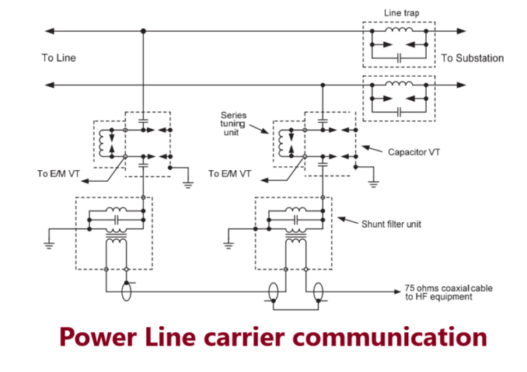
The high voltage capacitor is tuned by a tuning coil to present a low impedance at the signal frequency; the parallel circuit presents a high impedance at the signal frequency while providing a path for the power frequency currents passed by the capacitor.
It is necessary to minimise the loss of signal into other parts of the power system, to allow the same frequency to be used on another line. This is done with a ‘line trap’ or ‘wave trap’, which in its simplest form is a parallel circuit tuned to present a very high impedance to the signal frequency. It is connected in the phase conductor on the station side of the injection equipment.
The single frequency line trap can be treated as an integral part of the complete injection equipment to accommodate two or more carrier systems. However, difficulties may arise in an overall design because at certain frequencies the actual station reactance, which is normally capacitive, tunes with the trap which is inductive below its resonant frequency.
The result is a low impedance across the transmission path, preventing operation at these frequencies. This situation can be avoided by using an independent ‘double frequency’ or ‘broad-band’ trap. The attenuation of a channel is of prime importance in the application of carrier signalling because it determines the amount of transmitted energy available at the receiving end to overcome noise and interfering voltages.
The loss of each line terminal is 1 to 2dB through the coupling filter, a maximum of 3dB through its broad-band trap and not more than 0.5dB per 100 metres through the high frequency cable. The high frequency transmission characteristics of power circuits are good the loss amounting to 0.02 to 0.2dB per kilometre depending upon line voltage and frequency.
Line attenuation is not affected appreciably by rain, but serious increase in loss may occur when the phase conductors are thickly coated with hoar-frost or ice. Attenuations of up to three times the fair weather value have been experienced.
Receiving equipment commonly incorporates automatic gain control (AGC) to compensate for variations in attenuation of signals. High noise levels arise from lightning strikes and system fault inception or clearance. Although these are of short duration, lasting only a few milliseconds at the most, they may cause overloading of power line carrier receiving equipment.
PLCC components
Coupling Capacitor (C.C) = Couples high frequency carrier with Power Line ( 4000 to10000pF) Coupling capacitor connects the carrier equipment to the transmission line. The high capacitance offers low impedance to carrier frequency (1/ωC ) but high impedance to power frequency (50Hz).
Wave Trap / Line Trap (W.T) = Do not allow the transmitted HF carrier to enter inside the substation. (L = 0.5 to 2mH). The Wave trap offers high impedance (ωL) to HF carrier frequency and low impedance to Power frequency (50 Hz ).
Wave traps are used in high voltage transmission line to minimize undue loss of the carrier signal in the power station networks. Its impedance shall be negligible at power frequency (50 HZ) so as not to disturb the power transmission but must be relatively high over any frequency band appropriate to carrier transmission.
LMU = Line Matching Unit = For impedance matching between line and coaxial cable, includes high voltage protection devices like drainage coil(20mH), lightening arrestor(500V) and an earth switch.
PLCC Terminal = Translates Voice and data into High Frequency Carrier. Output Power =10 to 80W.
Application of Powe line carrier communication(PLCC)
Signalling systems used for intertripping in particular must incorporate appropriate security features to avoid maloperation. The most severe noise levels are encountered with operation of the line isolators, and these may last for some seconds. Although maloperation of the associated teleprotection scheme may have little operational significance, since the circuit breaker at one end at least is normally already open, high security is generally required to cater for noise coupled between parallel lines or passed through line traps from adjacent lines.
Signalling for permissive inter-trip applications needs special consideration, as this involves signalling through a power system fault. The increase in channel attenuation due to the fault varies according to the type of fault, but most utilities select a nominal value, usually between 20 and 30dB, as an application guide.
A protection signal boost facility can be employed to cater for an increase in attenuation of this order of magnitude, to maintain an acceptable signal-to-noise ratio at the receiving end, so that the performance of the service is not impaired. Most direct intertrip applications require signalling over a healthy power system, so boosting is not normally needed.
In fact, if a voice frequency intertrip system is operating over a carrier bearer channel, the dynamic operating range of the receiver must be increased to accommodate a boosted signal. This makes it less inherently secure in the presence of noise during a quiescent signalling condition.
Digital Power Line Carrier
The latest power line carrier equipment allows analogue, digital and mixed-mode communication. Digital communication up to 128kbits/s can be achieved using a 16kHz bandwidth. Low-latency Ethernet bridging facilities are a cost-effective communications solution for substations that have no access to any fibre network.
Frequently Asked Question (FAQ)
What is full name of PLCC?
PLCC-Power Line Carrier Communication
What is PLCC?
Power Line carrier Communication or Power Line Carrier (PLC) is a technology that it works narrow or broad band speeds through power lines by varies advanced modulation technology. This PLCC modem works in based on the principle of controlling or each electrical device has connected to an electrical socket with the existing power line in the building.
How to PLCC in Electrical substation?
PLCC system uses the same High Voltage transmission line connecting two sub-stations for telecommunication purpose too. PLCC is used in all power utilities as a primary communication service to transmit speech, telemetry and protection tripping commands. This is economic and reliable for inter grid message transfer as well as low bit rate RTU signals.
Which equipment used in PLCC in Electrical substation?
PLCC terminal, Coupling device, Wave trap, Line matching unit(LMU), battery set
What is Wave trap/Line trap?
Line traps shall be inserted into extra high voltage transmissions line to prevent undue loss of carrier signal for all power system conditions. Their impedance shall be negligible at power frequency (50 Hz) so as not to disturb power transmission but shall be relatively high over the frequency band appropriate to carrier transmission.
What is coupling device?
The coupling devices shall be interposed between the capacitor voltage transformer and coaxial line to the PLC transmitter/receiver. The coupling device, in conjunction with the capacitor voltage transformer, shall ensure efficient transmission of carrier frequency signals between the carrier frequency connection and the power line. In addition safety of personnel and protection of the low voltage parts and installation, against the effects of power frequency voltage and transient over voltages shall be ensured.
How high frequency cable(HFC) used in PLCC?
High frequency cable shall connect the coupling device installed in the switchyard to the PLC terminal installed indoors. The high frequency cables supplied by the Contractor shall be suitable for laying directly in trenches or in ducts.
Pingback: Optical communication in Electrical Power System
support those who suffer support those who suffer .
Thanks for appreciation
Please share my web to your friends group
Follow my social group
Thank you, I’ve just been searching for info approximately this topic for a
while and yours is the greatest I’ve found out so
far. But, what concerning the conclusion?
Are you certain in regards to the supply?
Hey there! This is kind of off topic but I need some guidance from an established blog.
Is it very hard to set up your own blog? I’m not
very techincal but I can figure things out
pretty quick. I’m thinking about making my own but I’m not
sure where to begin. Do you have any points or suggestions?
With thanks
Yes! Finally something about https://baleliterasi.org/.