
Table of Contents
ToggleWhat is Start and Stall protection of Motor?
When a motor is started, it draws a current well in excess of full load rating throughout the period that the motor takes to run-up to speed. While the motor starting current reduces somewhat as motor speed increases, it is normal in protection practice to assume that the motor current remains constant throughout the starting period. The starting current will vary depending on the design of the motor and method of starting.
For motors started DOL (direct-on-line), the nominal starting current can be 4-8 times full-load current. However, when a star-delta starter is used, the line current will only be 1/root(3) of the DOL starting current.
Should a motor stall whilst running, or fail to start, due to excessive loading, the motor will draw a current equal to its locked rotor current. It is not therefore possible to distinguish between a stall condition and a healthy start solely on the basis of the current drawn. Discrimination between the two conditions must be made based on the duration of the current drawn. For motors where the starting time is less than the safe stall time of the motor, protection is easy to arrange.
However, where motors are used to drive high inertia loads,the stall withstand time can be less than the starting time. In these cases, an additional means must be provided to enable discrimination between the two conditions to be achieved.
Excessive Start Time or Locked Rotor Protection
A motor may fail to accelerate from rest for a number of reasons: loss of a supply phase, mechanical problems, low supply voltage, excessive load torque.
A large current will be drawn from the supply, and cause extremely high temperatures to be generated within the motor. This is made worse by the fact that the motor is not rotating, and hence no cooling due to rotation is available. Winding damage will occur very quickly – either to the stator or rotor windings depending on the thermal limitations of the particular design (motors are said to be stator or rotor limited in this respect).
The method of protection varies depending on whether the starting time is less than or greater than the safe stall time. In both cases, initiation of the start may be sensed by detection of the closure of the switch in the motor feeder (contactor or CB) and optionally current rising above a starting current threshold value – typically 200% of motor rated current. For the case of both conditions being sensed, they may have to occur within a narrow aperture of time for a start to be recognised.
Special requirements may exist for certain types of motors installed in hazardous areas (e.g. motors with type of protection EEx ‘e’) and the setting of the relay must take these into account. Sometimes a permissive interlock for machine pressurisation (on EEx ‘p’ machines) may be required, and this can be conveniently achieved by use of a relay digital input and the in-built logic capabilities.
Start time less than safe stall time
Protection of Motor is achieved by use of a definite time overcurrent characteristic, the current setting being greater than full load current but less than the starting current of the machine. The time setting should be a little longer than the start time, but less than the permitted safe starting time of the motor.
Start time greater than or equals to safe stall time
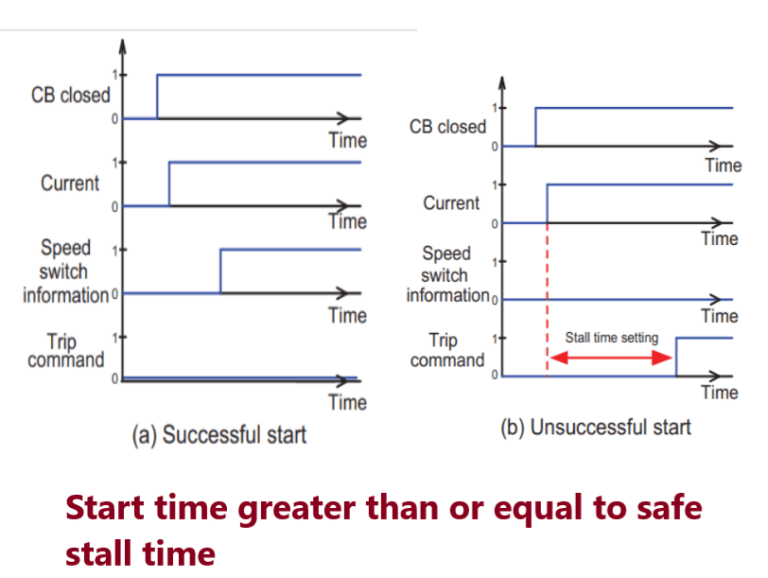
For this condition, a definite time overcurrent characteristic by itself is not sufficient, since the time delay required is longer than the maximum time that the motor can be allowed to carry starting current safely. An additional means of detection of rotor movement, indicating a safe start, is required. A speed-sensing switch usually provides this function.
Detection of a successful start is used to select the relay timer used for the safe run-up time of the motor. This time can be longer than the safe stall time, as there is both a (small) decrease in current drawn by the motor during the start and the rotor fans begin to improve cooling of the machine as it accelerates.
If a start is sensed by the relay through monitoring current and/or start device closure, but the speed switch does not operate, the relay element uses the safe stall time setting to trip the motor before damage can occur. Figure-A illustrates the principle of operation for a successful start, and Figure-B for an unsuccessful start.
Stall protection of Motor
Should a motor stall when running or be unable to start because of excessive load, it will draw a current from the supply equivalent to the locked rotor current. It is obviously desirable to avoid damage by disconnecting the machine as quickly as possible if this condition arises.
Motor stalling can be recognised by the motor current exceeding the start current threshold after a successful start – i.e. a motor start has been detected and the motor current has dropped below the start current threshold within the motor safe start time. A subsequent rise in motor current above the motor starting current threshold is then indicative of a stall condition, and tripping will occur if this condition persists for greater than the setting of the stall timer. An instantaneous overcurrent relay element provides protection.
In many systems, transient supply voltage loss (typically up to 2 seconds) does not result in tripping of designated motors. They are allowed to re-accelerate upon restoration of the supply. During re-acceleration, they draw a current similar to the starting current for a period that may be several seconds. It is thus above the motor stall relay element current threshold.
The stall protection would be expected to operate and defeat the object of the re-acceleration scheme. A motor protection relay will therefore recognise the presence of a voltage dip and recovery, and inhibit stall protection for a defined period. The under voltage protection element can be used to detect the presence of the voltage dip and inhibit stall protection for a set period after voltage recovery.
Protection against stalled motors in case of an unsuccessful reacceleration is therefore maintained. The time delay setting is dependent on the re-acceleration scheme adopted and the characteristics of individual motors. It should be established after performing a transient stability study for the re-acceleration scheme proposed.
Number of Starts limitation Motor
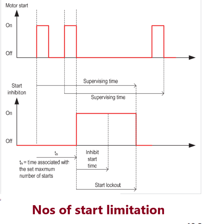
Any motor has a restriction on the number of starts that are allowed in a defined period without the permitted winding, etc. temperatures being exceeded. Starting should be blocked if the permitted number of starts is exceeded. The situation is complicated by the fact the number of permitted ‘hot’ starts in a given period is less than the number of ‘cold’ starts, due to the differing initial temperatures of the motor. The relay must maintain a separate count of ‘cold’ and ‘hot’ starts. By making use of the data held in the motor thermal replica, ‘hot’ and ‘cold’ starts can be distinguished.
To allow the motor to cool down between starts, a time delay may be specified between consecutive starts (again distinguishing between ‘hot’ and ‘cold’ starts). The start inhibit is released after a time determined by the motor specification.
In this example, the maximum number of starts within the Supervising Time has been reached, therefore the Inhibit Start Time is initiated. The remaining time is greater than the Inhibit Start Time, so the start inhibition remains for a duration equal to the supervising time minus the tn.
Thanks for sharing. I read many of your blog posts, cool, your blog is very good.