Transformer Differential Protection
Percentage differential protection is used for large power transformers above 5 MVA rating for the protection against internal short circuit. It cannot detect incipient faults.

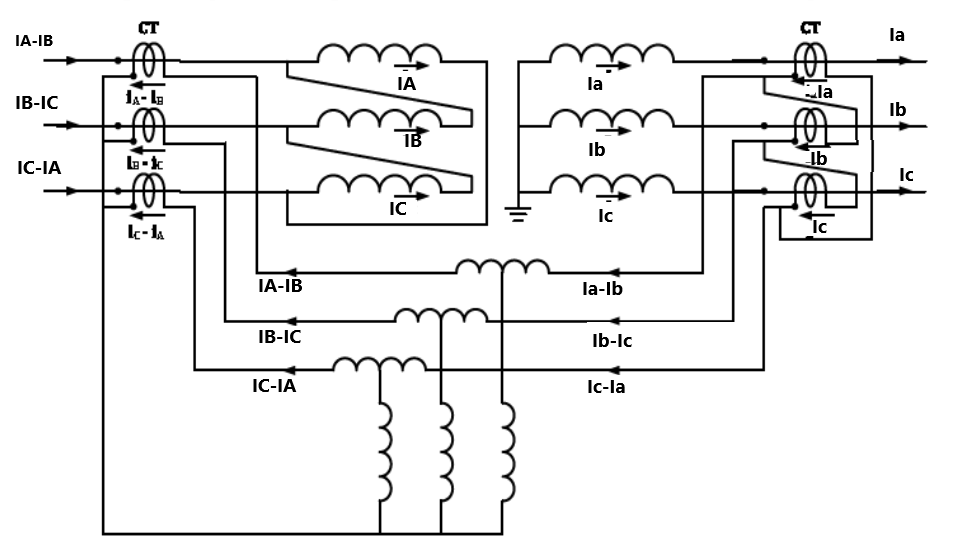
The connections of differential protection is carried out in such a way that under normal conditions or external faults the current flowing through relay operating coil is zero i.e. both CT secondary currents are in opposite direction that keeps relay inoperative.
When internal fault occurs in the winding, the polarity of the induced emf of the one of CT secondary gets reversed and hence current flowing through relay operating coil is non zero i.e. both CT secondary current are in same direction that makes relay to operate.
To feed the same CT secondary current in relay operating coil, CT placed at star side of transformer are connected in delta and CT placed at delta side of transformer are connected in star.
For Y–Δ connected transformer always there is a phase shift of 30° in line currents, above mentioned CT secondary connection corrects this phase shift also.
Zero sequence current flowing on the star side of the transformers does not produce current outside the delta on the other side, hence zero sequence current should be eliminated from the star side. Above mentioned CT secondary connection also fulfill this condition.
For Y-Y connected transformer, CT secondary is connected in delta. When start point is not earthed, CT secondary may be connected in star on both sides. If Y-Y connected transformer with star point earthed and CT secondary are connected in star, the relay operates for external faults.
Differential protection relay settings for transformer are kept higher than that of alternators.
Operating coil setting : 40% for transformer & 10% for generator
Bias setting : 10% for transformer & 5% for generator
The reasons for a higher setting for transformer protection are
- Transformer is provided with on load tap changer but CT ratio cannot be changed with varying transformation ratio. It is kept to suit the nominal voltage ratio of transformer. Hence for the tappings other than nominal voltage, differential current flows through relay operating coil during load and external fault conditions.
- When a transformer is on no-load, its primary draws no-load current and secondary does not draw any current, hence differential current flows through relay operating coil. Relay setting is kept higher than no-load current.
Difficulties in operation of differential protection of transformer
Transformer differential protection suffers for several implementation difficulties as:
Due to change in voltage rating of transformer primary and secondary, voltage rating of CT used in primary and secondary are also different. Sometimes it is possible that the CT on both the sides are from different manufacturers, hence saturation characteristics of both side CT are not identical. These non-identical CT cause high differential current to flow through relay operating coil for heavy external fault. This unwanted relay tripping is avoided by using biased differential relay.
Full load current of the transformers on primary and secondary sides are different, CT ratio on both the sides have to be selected such that current in pilot wire are same on both sides.
When transformer is loaded, primary draws sum of rated current and no-load current. CT ratios are selected considering rated transformation ratio, hence some differential current always flow through relay operating coil due to the no-load current component of the primary current. This does not cause any problem to differential relay operation as no-load current of large transformers is 1–2% of the rated current and basic setting (pickup setting) of the relay is set higher than this small spill current.
CT used for differential protection has ratio errors at the normal rated current. At the time of external fault, CT primary currents are excessive that creates considerable inherent difference in CT characteristic that further makes the large difference in CT secondary current and maloperate differential relay.
Power transformers are always provided with the tappings to regulate the output voltage as required by loading conditions while CT ratios are selected on the basis of a normal tap. Once the tap is changed, the pilot wire currents on both sides no more remains same. Some differential current flows through the relay operating coil that may operate the relay, particularly for high through fault currents.
An instantaneous change in flux linkages in a power transformer causes large magnetizing currents to flow, specifically when an unloaded transformer is energized or short circuit occurs at loaded transformer and it is disconnected. Increased magnetizing current makes the large difference in CT secondary current and maloperate differential relay.
When the primary voltage of a transformer exceeds the rated value, the magnetizing current also increases. For large modern transformers, a 20% increase in voltage increases the magnetization current four times. This makes the large difference in CT secondary current and maloperate differential relay.


Pingback: Differential Relay testing procedure