
What is Transformer Turns Ratio Test?
The turns ratio test is an AC low voltage test which determines the ratio of the high voltage winding to all other windings at no-load. The turns ratio test is performed on all taps of every winding.
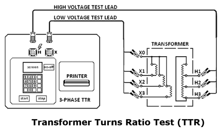
The Transformer Turns Ratio tester (TTR) is device used to measure the turns ratio between the windings (example shown below). Voltage is applied on the H marked leads and measured of the X marked lead by the test set.
Ratio measurements are conducted on all tap positions and calculated by dividing the induced voltage reading into the applied voltage value.
When ratio tests are being made on three-phase transformers, the ratio is taken on one phase at a time with a three-phase TTR until the ratio measurements of all three phases are completed. Measured ratio variations should be within 0.5% of the nameplate markings.
Step of Transformer Turns Ratio Test
1)Isolate the equipment, apply working grounds to all incoming and outgoing cables and disconnect all incoming and outgoing cables from the transformer bushing terminals connections.
Disconnected cables should have sufficient clearance from the switchgear terminals greater than the phase spacing distance.
Use nylon rope to hold cable away from incoming and outgoing terminals as required.
2)Connect the H designated three-phase test lead with the military style connector at one end to the mating connection on the test set marked with an H.
Ensure that the connector’s index notch lines up properly.
3)Connect the X designated three-phase test of lead military style connector at one end to the mating (coupling) connection on the test set marked with an X.
Ensure that the connector’s index notch lines up properly.
4)Connect the H1,H2,H3 designated test lead to the corresponding H1, H2,H3 transformer terminal/ bushing.
Connect the H0 test lead if H0 terminal/bushing is present.
5)Connect the X1,X2,X3 designated test leads to the corresponding X1,X2,X3 transformer terminals/ bushings.
Connect the X0 test lead if X0 terminal/bushing is present.
6) Perform turns ratio measurements for all tap positions.
7) Confirm that the measured ratios is within 0.5% of the calculated ratios.
Reading your article helped me a lot and I agree with you. But I still have some doubts, can you clarify for me? I’ll keep an eye out for your answers.