
Table of Contents
ToggleIntroduction
There are several ways in which the switching equipment can be connected in the electrical layout of substation. The selection of the schemes is in general affected by following aspects:
- Degree of flexibility of operations desired.
- Importance of load and local conditions. Freedom fromtotal shutdown and its period desired.
- Economic consideration, availability and cost.
- Provision of extension.
- Maintenance, safety of personnel.
The commonly used bus bar schemes at Sub Stations are:
- Single bus bar.
- Main and Transfer bus bar.
- Double bus bar.
- Double main and transfer bus bar.
- One and a half breaker scheme.
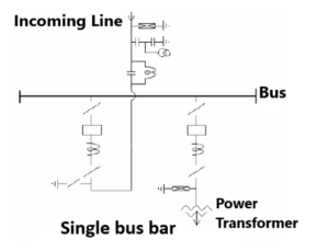
Single bus bar scheme
This is the simplest switching scheme in which each circuit is provided with one circuit breaker. This arrangement offers little security against bus bar faults and no switching flexibility resulting into quite extensive outages of bus bar and frequent maintenance of bus bar isolator. The entire Sub Station is lost in case of a fault on the bus bar or on any bus bar isolator and also in case of maintenance of the bus bar. Another disadvantage of this switching scheme is that in case of maintenance of circuit breaker, the associated feeder has also to be shutdown.
Main and Transfer bus bar
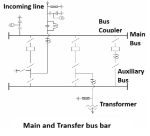
This is technically a single bus bar arrangement with an additional bus bar called “Auxiliary bus” energized from main bus bars through a bus coupler circuit, i.e., for ‘n’ number of circuits, it employs ‘n + 1’ circuit breakers. Each circuit is connected to the main bus bar through a circuit breaker with isolators on both sides and can be connected to the auxiliary bus bar through an isolator.
The additional provision of bus coupler circuit (Auxiliary bus)facilitates taking out one circuit breaker at a time for routine overhaul and maintenance without de – energizing the circuit controlled by that breaker as that circuit then gets energized through bus coupler breaker.
As in the case of single bus arrangement, this scheme also suffers from the disadvantages that in the event of a fault on the main bus bar or the associated isolator, the entire substation is lost. This bus arrangement has been extensively used in 132 kV Sub Stations.
Double bus bar
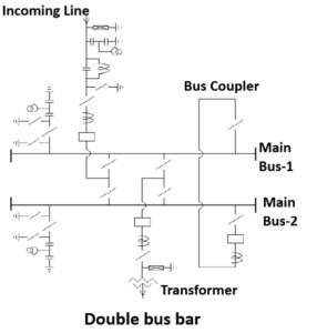
In this scheme, a double bus bar arrangement is provided. Each circuit can be connected to either one of these bus bars through respective bus bar isolator. Bus coupler breaker is also provided so that the circuits can be switched on from one bus to the other on load. This scheme suffers from the disadvantage that when any circuit breaker is taken out for maintenance, the associated feeder has to be shut down. This Bus bar arrangement was generally used in earlier 220 kV sub stations.
Double main and transfer bus bar
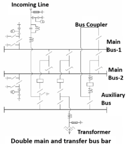
The limitation of double bus bar scheme can be overcome by using additional Auxiliary bus, bus coupler breaker and Auxiliary bus isolators. The feeder is transferred to the Auxiliary bus during maintenance of its controlling circuit breaker without affecting the other circuits. This Bus bar arrangement is generally used nowadays in 220kV sub stations.
One and a half breaker scheme
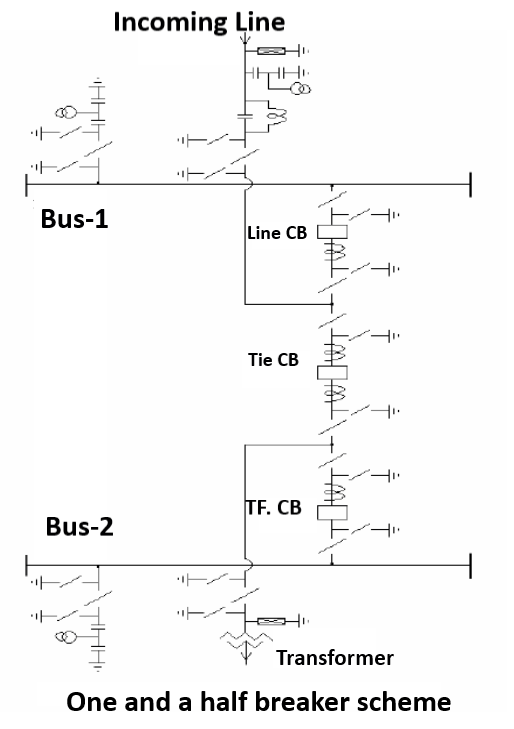
In this scheme, three circuit breakers are used for controlling two circuits which are connected between two bus bars. Normally, both the bus bars are in service. A fault on any one of the bus bars is cleared by opening of the associated circuit breakers connected to the faulty bus bar without affecting continuity of supply. Similarly, any circuit breaker can be taken out for maintenance without causing interruption.
Load transfer is achieved through the breakers and, therefore, the operation is simple. However, protective relaying is somewhat more involved as the central (tie) breaker has to be responsive to troubles on either feeder in the correct sequence. Besides, each element of the bay has to be rated for carrying the currents of two feeders to meet the requirement of various switching operations which increases the cost.
The breaker and a half scheme is best for those substations which handle large quantities of power and where the orientation of out going feeders is in opposite direction. This scheme has been used in the 400 kV substations.
Pingback: Accessories used in Electrical Substation
Your point of view caught my eye and was very interesting. Thanks. I have a question for you. https://accounts.binance.info/en/register-person?ref=JHQQKNKN