
Table of Contents
ToggleWhat is Relay?
It is necessary to remove a fault from the power system as quickly as possible for healthy power system. So Relay sense the abnormal fault and give command to circuit breaker to trip and isolate faulty section from healthy section.
However, the relay must make its decision based upon voltage and current waveforms, which are severely distorted due to transient phenomena that follow the occurrence of a fault. The relay must separate the meaningful and significant information contained in these waveforms upon which a secure relaying decision must be based.
Types of Relay in power system
Various types of relay used in power system as per their application.
Electromechanical Relays
Static Relays
Digital Relays
Numerical Relays
Electromechanical Relays
These relays were the earliest forms of relay used for the protection of power systems, and they date back around 100 years. They work on the principle of a mechanical force operating a relay contact in response to a stimulus.
The mechanical force is generated through current flow in one or more windings on a magnetic core or cores, hence the term electromechanical relay. The main advantage of such relays is that they provide galvanic isolation between the inputs and outputs in a simple, cheap and reliable form.
Therefore these relays are still used for simple on/off switching functions where the output contacts carry substantial currents. Electromechanical relays can be classified into several different types as follows:
Attracted armature
Moving coil induction
Thermal
Motor operated
Mechanical
However, Only attracted armature types presently have significant applications while all other types have been superseded by more modern equivalents.
Attracted Armature Relays
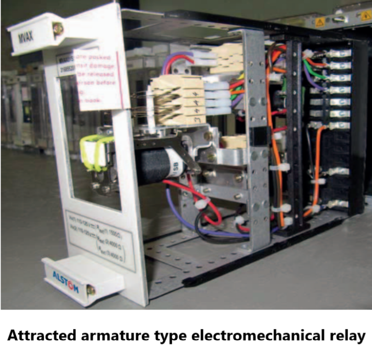
These generally consist of an iron-cored electromagnet that attracts a hinged armature when energised. A restoring force is provided by a spring or gravity so that the armature returns to its original position when the electromagnet is de-energised. Typical forms of an attracted armature relay are shown in Figure Movement of the armature opens or closes a contact.
The armature either carries a moving contact that engages with a fixed one or causes a rod to move that brings two contacts together. It is easy to mount multiple contacts in rows or stacks, causing a single input to actuate several outputs. The contacts can be robust and therefore able to make, carry and break large currents under difficult conditions such as highly inductive circuits. This is still a significant advantage of this type of relay that ensures its continued use.
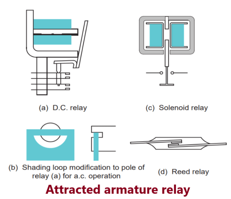
The energising quantity can be either an a.c. or a d.c. current. If an a.c. current is used, there is chatter due to the flux passing through zero every half cycle. A common solution is to split the magnetic pole and provide a copper loop around one half. The flux is then phase-shifted in that pole so the total flux is never equal to zero.
Conversely, for relays energised using a d.c. current, remanent flux may prevent the relay from releasing when the actuating current is removed. This can be avoided by preventing the armature from contacting the electromagnet by a non-magnetic stop, or constructing the electromagnet using a material with very low remanent flux properties.
Operating speed, power consumption and the number and type of contacts required are a function of the design. The typical attracted armature relay has an operating speed of between 100ms and 400ms, but reed relays (whose use spanned a relatively short period in the history of protection relays) with light current contacts can be designed to have an operating time of as little as 1ms. Operating power is typically 0.05-0.2 watts, but could be as large as 80 watts for a relay with several heavy-duty contacts and a high degree of resistance to mechanical shock.
Static relays
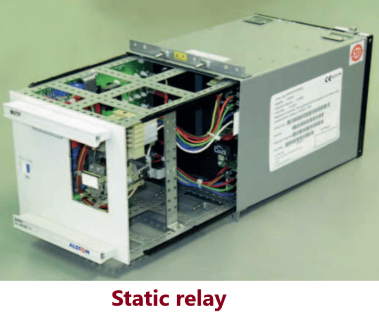
The term ‘static’ implies that the relay has no moving parts. This is not strictly the case for a static relay, as the output contacts are still generally attracted armature relays. In a protection relay, the term ‘static’ refers to the absence of moving parts to create the relay characteristic.
Their design is based on the use of analogue electronic devices instead of coils and magnets to create the relay characteristic. Early versions used discrete devices such as transistors and diodes with resistors, capacitors and inductors.
advances in electronics enabled the use of linear and digital integrated circuits in later versions for signal processing and implementation of logic functions. Although basic circuits were common to several relays, each protection function had its own case, so complex functions required several cases of interconnected hardware.
User programming was restricted to the basic functions of adjustment of relay characteristic curves. Therefore they can be considered as an analogue electronic replacement for electromechanical relays, with some additional flexibility in settings and some saving in space requirements. In some cases, relay burden is reduced, reducing CT/VT output requirements.
The d.c. supply can be generated from the measured quantities of the relay, this has the disadvantage of increasing the burden on the CTs or VTs, and there is a minimum primary current or voltage below which the relay will not operate. This directly affects the possible sensitivity of the relay. So provision of an independent, highly reliable and secure source of relay power supply was an important consideration.
To prevent maloperation or destruction of electronic devices during faults or switching operations, sensitive circuitry is housed in a shielded case to exclude common mode and radiated interference. The devices are also sensitive to electrostatic discharge (ESD), requiring special precautions during handling. ESD damage may not be immediately apparent but may cause premature failure of the relay.
Digital relays
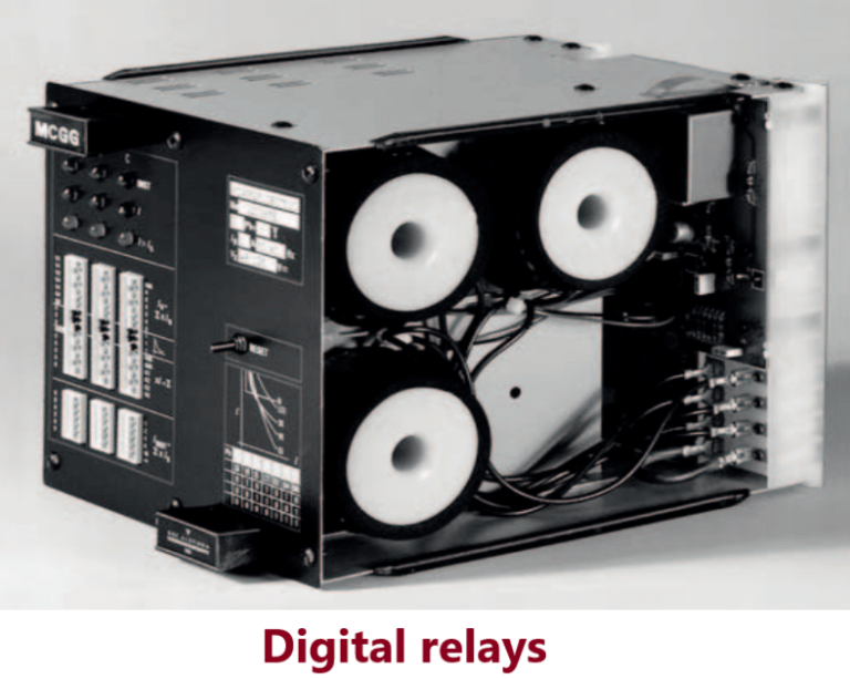
Digital protection relays introduced a step change in technology. Microprocessors and microcontrollers replaced analogue circuits used in static relays to implement relay functions. Early examples were introduced around 1980 and with improvements in processing capacity are still current technology for many relay applications. However, such technology could be completely superseded by numerical relays.
Compared to static relays, digital relays use analogue to digital conversion of all measured quantities and use a microprocessor to implement the protection algorithm. The microprocessor may use a counting technique or use Discrete Fourier Transforms (DFT) to implement the algorithm.
However, these microprocessors have limited processing capacity and associated memory compared to numerical relays. Therefore the functionality is limited mainly to the protection function itself. Compared to an electromechanical or static relay, digital relays have a wider range of settings, greater accuracy and a communications link to a remote computer. Figure 7.5 shows a typical digital relay.
Digital relays typically use 8 or 16-bit microprocessors that were later used in modems, hard disk controllers or early car engine management systems. The limited power of the microprocessors used in digital relays restricts the number of samples of the waveform that can be measured per cycle.
This limits the speed of operation of the relay in certain applications. Therefore a digital relay for a particular protection function may have a longer operation time than the static relay equivalent. However, the extra time is insignificant compared to overall tripping time and possible effects on power system stability.
Numerical relays
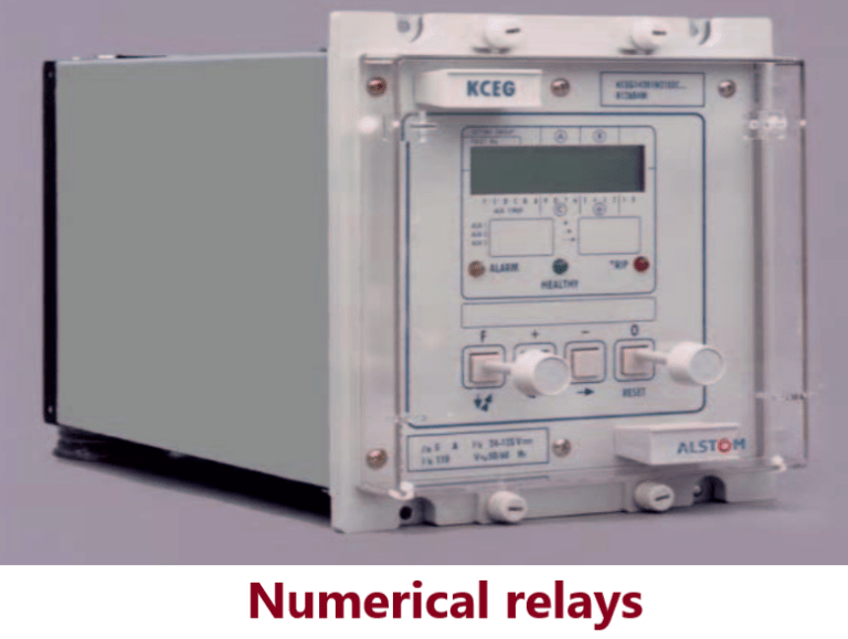
The distinction between digital and numerical relays is particular to Protection. Numerical relays are natural developments of digital relays due to advances in technology. They use one or more digital signal processors (DSP) optimised for real time signal processing, running the mathematical algorithms for the protection functions.
The continuing reduction in the cost and size of microprocessors, memory and I/O circuitry leads to a single item of hardware for a range of functions. For faster real time processing and more detailed analysis of waveforms, several DSPs can be run in parallel.
A numerical relay has the functionality that previously required several discrete relays, therefore the relay functions such as overcurrent or earth fault are referred to as ‘relay elements’. Each relay element is in software so with modular hardware the main signal processor can run a vast variety of relay elements.
The argument against putting many features into one piece of hardware centres on the issues of reliability and availability. A failure of a numerical relay may cause many more functions to be lost, compared to applications where different functions are implemented by separate hardware items. Comparison of reliability and availability between the two methods is complex as inter-dependency of elements of an application provided by separate relay elements needs to be taken into account.
With the experience gained with static and digital relays, most hardware failure mechanisms are now well understood and suitable precautions taken at the design stage. Software problems are minimised by rigorous use of software design techniques, extensive prototype testing and the ability to download updated software.
Frequently Asked Question (FAQ)
What is a relay in a power system? A relay in a power system is an electrically operated switch that detects abnormal conditions (such as overcurrent, overvoltage, or faults) and initiates a response to protect the system from damage.
What are the types of relays used in power systems? There are several types of relays used in power systems, including:
- Overcurrent relays: These protect against excessive currents in a circuit.
- Overvoltage relays: They protect against voltage spikes or sustained overvoltages.
- Undervoltage relays: These protect against voltage drops below a specified level.
- Distance relays: Used to protect transmission lines by measuring the impedance to faults.
- Differential relays: They compare currents entering and leaving a protected zone to detect internal faults.
- Frequency relays: Protect against deviations in power system frequency.
- Directional relays: They respond based on the direction of power flow, useful in complex interconnected grids.
How do relays work in a power system? Relays typically monitor electrical parameters (like current, voltage, frequency) using sensors. When abnormal conditions are detected, the relay actuates its contacts to open or close circuits, thereby isolating the faulted section of the power system or signaling for corrective action.
What factors should be considered when selecting relays for a power system? Factors include the specific application (transmission, distribution, generation), the type and magnitude of faults expected, response time requirements, environmental conditions, and the integration with other protection schemes.
What are the main functions of relays in electrical substations? Relays in electrical substations serve several critical functions:
- Fault Detection: They detect abnormal electrical conditions like short circuits or overloads.
- Isolation: Relays initiate the opening of circuit breakers to isolate faulty sections of the network.
- Protection Coordination: They coordinate with other relays and protective devices to ensure selective operation, minimizing downtime.
- Monitoring: Relays monitor parameters such as current, voltage, frequency, and phase angle to maintain system stability.
Pingback: Protective Relay testing- Type test on Protective Relay
Pingback: Frequent Tripping of feeder on earth fault after faulty CT replacement