
Table of Contents
ToggleDefinition of Loss
Loss in any machine is broadly defined as difference between input power and output power.An electrical transformer is an static device, hence mechanical losses (like Windage or friction losses) are absent in it and only electrical losses are observed.
Classification of Transformer Losses
Losses are important for the operation of transformer and efficiency calculation. Since transformer has no rotational loss it has higher efficiency than any other electrical machine.

Copper Loss
These losses occur in the windings of the transformer when heat is dissipated due to the current passing through the windings and the internal resistance offered by the windings. So these are also known as ohmic losses or I²R losses, where ‘I’ is the current passing through the windings and R is the internal resistance of the windings.
These losses are present both in the primary and secondary windings of the transformer and depend upon the load attached across the secondary windings since the current varies with the variation in the load, so these are variable losses.
Copper losses occur only when the transformer is supplying power to a load. As the load current increases, the copper losses also increase, since they are directly proportional to the square of the load current.
Copper losses represent a significant portion of the total losses in a transformer, particularly in smaller transformers and at higher load currents. Minimizing copper losses is crucial for improving the overall efficiency and performance of the transformer.
Calculation of Copper Loss as per below formula
Ohmic = I²pRp + I²sRs
According to Ohm’s law, the power dissipated as heat (P) in a resistor is proportional to the square of the current (I) passing through it and its resistance (R). Mathematically, this relationship is expressed as P = I²R.
How to reduce Copper Loss
To reduce copper losses, transformer windings are typically designed with materials that have low electrical resistance, such as high-purity copper or aluminum. Additionally, increasing the cross-sectional area of the conductors reduces their resistance, thereby lowering copper losses. However, increasing the conductor size also leads to larger and more expensive transformers.
Core Loss
These losses occur in the core of the transformer. These losses depend upon the magnetic properties of the materials which are present in the core, so they are also known as iron losses, as the core of the transformer is made up of iron.
And since they do not change like the load, so these losses are also constant. There are two types of Iron losses in the transformer:
Hysteresis losses
Eddy Current losses
Hysteresis losses
Hysteresis loss is due to reversal of magnetization in the transformer core.When the magnetization force beyond coercive force is applied all the magnetic domain are oriented in reverse direction. For every cycle due to this domain reversal, there will be extra work done. For this reason, there will be a consumption of electrical energy which is known as Hysteresis loss of transformer.
In technical terms, hysteresis losses in a transformer are the energy losses associated with the repeated magnetization and demagnetization of the transformer core material as it is subjected to alternating magnetic fields during operation.
Magnetization and Demagnetization:
When the transformer core material, typically made of ferromagnetic substances like iron or steel, is exposed to an alternating magnetic field generated by the current flowing through the transformer windings, its magnetic domains align with the magnetic field.
As the direction of the magnetic field changes with alternating current, the magnetic domains in the core material repeatedly reorient themselves to follow the changing field.
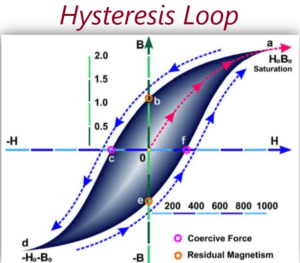
Hysteresis Loop
Due to the physical properties of ferromagnetic materials, there is a lag or delay in the alignment and realignment of the magnetic domains, known as hysteresis. This lag results in a characteristic hysteresis loop on a magnetization curve, representing the relationship between the magnetic flux density (B) and the magnetizing force (H). Energy is required to move the material around this loop during each magnetization and demagnetization cycle.
Energy Dissipation
The area enclosed by the hysteresis loop represents the energy dissipated as heat during each cycle of magnetization and demagnetization. This energy loss occurs due to the internal friction and molecular rearrangement within the core material as it repeatedly switches its magnetization direction. The dissipated energy manifests as heat within the core material, contributing to hysteresis losses.
Hysteresis Loop
Due to the physical properties of ferromagnetic materials, there is a lag or delay in the alignment and realignment of the magnetic domains, known as hysteresis. This lag results in a characteristic hysteresis loop on a magnetization curve, representing the relationship between the magnetic flux density (B) and the magnetizing force (H). Energy is required to move the material around this loop during each magnetization and demagnetization cycle.
How to reduce Hysteresis loss
To minimize hysteresis losses, transformer cores are often constructed using materials with low coercivity and remanence, such as silicon steel or other specialized alloys. These materials exhibit smaller hysteresis loops, resulting in reduced energy loss during operation. Additionally, operating transformers at lower frequencies can help decrease the frequency of magnetization cycles per unit time, thereby reducing hysteresis losses.
Calculation Formula
Hysteresis loss for given frequency ‘f’=Area enclosed within one hysteresis loop * f Mathematically, it can be defined using Steinmentz formula as
Wh= η Bmax ˣ f V (watts)
where, η = Steinmetz hysteresis constant, V = volume of the core in m3, x= Steinmetz exponent=1.5 to 2.5, B-Flux
Eddy Current Loss
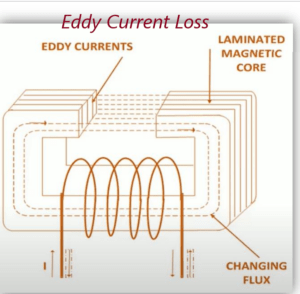
Because of time variation of flux flowing through the magnetic material, current is induced in the magnetic material, following Faraday’s law. This current is called eddy current. It will not contribute in output of the transformer and dissipated as heat. This type of energy loss is called eddy current loss.
The eddy current losses refer to the dissipation of energy in the form of heat due to the circulation of induced currents within conductive materials subjected to a changing magnetic field.
The presence of these eddy currents creates their own magnetic fields, which interact with the original magnetic field that induced them. According to Lenz’s law, the direction of the eddy currents opposes the change in magnetic flux that induced them. As a result, energy is expended to overcome the resistance within the material, leading to the conversion of electrical energy into heat.
The magnitude of eddy current losses depends on various factors, including the frequency of the alternating magnetic field, the conductivity and thickness of the material, and the geometry of the conductor.
How to reduce eddy current loss
To minimize eddy current losses in transformers and other electromagnetic devices, materials with high electrical resistivity, such as laminated iron or steel cores, are often used. Additionally, the core may be constructed from laminations to reduce the size of the eddy current loops and mitigate energy loss.
Calculation Formula of eddy current loss
We = KB2max*f2*t2 Watt
Where K = Constant of Eddy Current, t = thickness of lamination, B-Flux
Minor Losses
Stray loss is the additional loss takes place in auxiliary part of the transformer due to the presence of leakage flux. It is consider as variable loss.
Dielectric loss is takes place in transformer insulation and depends on the applied voltage. It is consider as constant loss.
Dielectric loss is takes place in transformer insulation and depends on the applied voltage. It is consider as constant loss.
Pingback: What is Eddy Current and Eddy Current loss
Pingback: All day Efficiency of Transformer
Your article helped me a lot, is there any more related content? Thanks! https://accounts.binance.com/en-NG/register?ref=YY80CKRN