
Table of Contents
ToggleDefinition
Directional feature is realized by comparing the direction of flow of line current with reference to the bus voltage i.e. directional relay measures phase angle between voltage and current.
Hence it is dual input and a phase comparator type relay. Voltage input signal is fed through bus potential transformer (PT) to relay voltage coil and current input signal is fed through line current transformer (CT) to relay current coil.
Directional over current relay operates only when current in relay coil is greater than its plug setting and flowing through the relay coil in its correct direction.
Working Principle
Working principle of directional relay is same as that of an induction disc relay i.e. torque produced by relay coils are due to the iteration of flux produced by one coil with current of second coil.
As shown in Fig-1,Let flux Φ1 is setup by voltage coil and Φ2 is setup by current coil, induces eddy current in disc that further produces torque and rotates the disc.
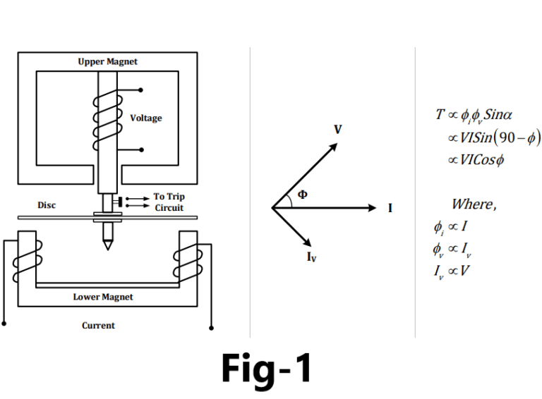
When angle Φ-90°, the torque produced is positive i.e. when angle between voltage and current decreases, torque increase.
For angle Φ>+90° and Φ<-90°, the torque produced is negative that tries to rotate induction disc or cup in reverse direction but this movement is hindered by backstop.
Relay continuously measures angle between voltage and current irrespective of its magnitude. When fault occurs, the value of fault current is sufficiently high but the value of voltage depends upon location of fault.
The actuating mechanism of the relay has to compensate for frictional torque and slight spring bias to avoid mal-operation due to vibration. Some minimum amount of torque is required for this compensation. A certain minimum value of voltage i.e. certain minimum distance of fault from the relay requires. If fault occurs up to this distance even if the direction is correct, relay does not operate. This region is known as dead zone.
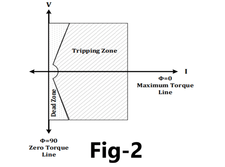
As shown in Fig-2,When angle Φ=0°, the torque produced is maximum. The line at which Φ=0° is called maximum torque line (MT line). But maximum torque angle at Φ=0° has no meaning because when fault occurs angle between voltage and current varies between Φ=70° to Φ=90° depending on location of fault.
At a particular relay location, for power flows in the normal direction, the relay is connected to produce negative torque i.e. angle between voltage and current of relay coils is kept (180 – Φ) to produce negative torque.
At the time of fault the power flows in the reverse direction then the relay produces a positive torque and it operates. In this condition, angle between voltage and current of relay coils is kept less than 90° to produce a positive torque.
For normal flow of power, the relay is supplied with V and – I but when reverse power flows due to fault, relay is supplied with V and I i.e. torque becomes positive. It is achieved easily by reversing the current coil.
Directional power Relay Connections
At the time of fault, voltage and power factor at fault point becomes low so directional relay cannot develop sufficient torque for its operation and if relay is designed to develop torque proportional to VI cosΦ, than this problem can never be overcome.
Hence to develop sufficient torque during all types of faults, irrespective of their locations,the relay connections are to be modified.
Each relay is energized by current from its respective phase and voltage from the other two phases. Two methods of connections are being carried out as
30° connection
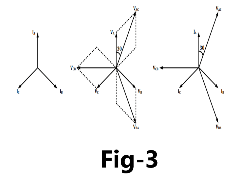
As shown in Fig-3,For phase A, current coil of the relay is energized by phase current IA and voltage coil is energized by line voltage VAC. For phase B, current coil of the relay is energized by phase current IB and voltage coil is energized by line voltage VBA.
For phase C, current coil of the relay is energized by phase current IC and voltage coil is energized by line voltage VCB. The relay is designed to develop maximum torque when its current and voltage are in phase i.e. system power factor is 0.866 (lag).
90° connection
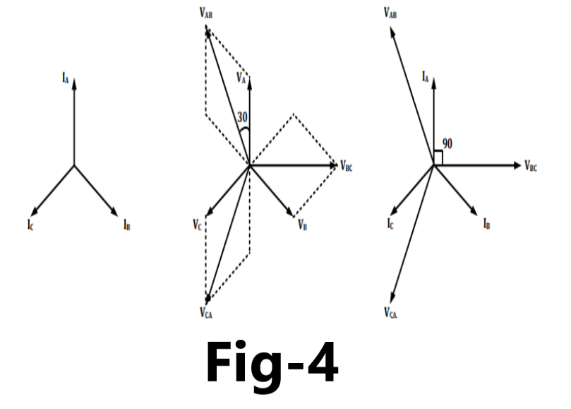
As per shown in Fig-4,For phase A, current coil of the relay is energized by phase current IA and voltage coil is energized by line voltage VBC. For phase B, current coil of the relay is energized by phase current IB and voltage coil is energized by line voltage VCA.
For phase C, current coil of the relay is energized by phase current IC and voltage coil is energized by line voltage VAB.The relay is designed to develop maximum torque when relay current leads voltage by 45°.
Application
Directional overcurrent relay protect transmission/distribution line from overcurrent.
Direction reverse power relay protect generator from motoring.

Pingback: Directional overcurrent relay protection in Power system
Pingback: Plug setting (PSM) and Time setting multiplier in Overcurrent protection of Transmission line - Electricalsphere
Why is it necessary to put directional relay and prevent reverse power flow in a transformer with delta-wye winding?