Table of Contents
ToggleWhat is Power Swing?
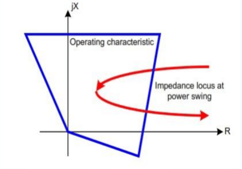
Power Swing which is basically caused by the large disturbances in the power system which if not blocked could cause wrong operation of the distance relay and can generates wrong or undesired tripping of the transmission line circuit breaker.
Power swing is a variation in three-phrase power flow which occurs when the generator angles are advancing or retarding relative to each other in response to changes in load magnitudes, line switching, loss of generation, faults, and other system disturbance.
It can cause major power outages, even power blackout or severe damage to the machine.
Thereby, a Power Swing Block (PSB) function is adopted in modern relays to prevent unwanted distance relay element operation during power swing.
The main purpose of the PSB function is to differentiate between power faults and power swings, and block distance or other relay elements from operations during a power swing.
Power swing effect on distance relay

Power swings can cause the load impedance to enter into the relay’s operating characteristic which under steady state conditions is not within the relay’s operating characteristic as shown in figure.
Distance or other relays should not trip during such as stable or unstable power swings, and allow the power system to return to a stable operating condition.
Faults that occur during a power swing must be detected and cleared with a high degree of selectivity and dependability.

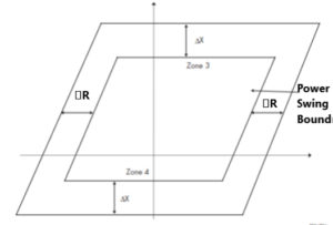
A fault on the system results in the measured impedance crossing rapidly crossing the DR Band, en route to a tripping zone.
Power swing is detected when three phase-phase impedances remained within the DR band for a time delay.
It is recommended to block all the zones in the distance relay for a time delay of 2 seconds to avoid unwanted tripping. (For stable power swing).
How to identify power swings?
The rate of change of impedance phasor is slower during power swings whereas faster for short circuit faults.
Power swing impedances vectors will normally enter the protection zones at an angle of 90 deg to the line angle.
Direction of current flow will remain same during the power swing event. Only voltages change with respect to one another.
Causes severe oscillations in power flow.
Power swing detection methods
Traditional Method
We can distinguish a Power Swing condition or OSS condition by the difference in the rate of change of the positive-sequence impedance vector.
This detection method is based on the fact that it takes a certain time for the rotor angle to advance because of system inertias.
Practical implementation of measuring the rate of change of the impedance is normally performed through the use of two impedance measurement elements together with a timing device.
If the measured impedance stays between the settings of the two impedance measurement elements for a predetermined time, the relay declares a power swing condition and issues a blocking signal to block the distance relay element operation.
Advanced Method
The advent of digital technology has given relay design engineers the ability to develop and realize new methods for detecting power swings.
Some of these new methods determine a power swing condition based on a continuous impedance calculation.
For example, an impedance calculation is performed for each 5ms step, and compared with the previous 5ms’ result. Thus two continuous deviations can be predicted as traveling impedance because of power swing.
Synchro phasor-based Out-of-Step Relaying measurement has also been used to detect and take action for power swings.
Many utilities are currently evaluating the use and application of synchronized phasor measurement systems.


You made several fine points there. I did a search on the issue and found mainly persons will have the same opinion with your blog.
I will immediately clutch your rss feed as I can’t to find your email subscription hyperlink or newsletter service. Do you have any? Kindly allow me understand in order that I may just subscribe. Thanks.
What’s Going down i am new to this, I stumbled upon this I’ve found It absolutely useful and it has aided me out loads. I am hoping to give a contribution & help other users like its helped me. Great job.