
Table of Contents
ToggleTripping Circuit
There are three main circuits in use for circuit breaker tripping:
Series sealing
Shunt reinforcing
Shunt reinforcement with sealing
For electromechanical relays, electrically operated indicators, actuated after the main contacts have closed, avoid imposing an additional friction load on the measuring element, which would be a serious handicap for certain types. Care must be taken with directly operated indicators to line up their operation with the closure of the main contacts. The indicator must have operated by the time the contacts make, but must not have done so more than marginally earlier. This is to stop indication occurring when the tripping operation has not been completed.
With modern digital and numerical relays, the use of various alternative methods of providing trip circuit functions is largely obsolete. Auxiliary miniature contactors are provided within the relay to provide output contact functions and the operation of these contactors is independent of the measuring system, as mentioned previously.
The making current of the relay output contacts and the need to avoid these contacts breaking the trip coil current largely dictates circuit breaker trip coil arrangements. Comments on the various means of providing tripping arrangements are, however, included below as a historical reference applicable to earlier electromechanical relay designs.
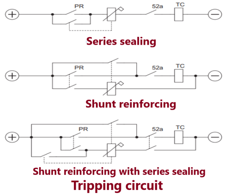
Series sealing
The coil of the series contactor carries the trip current initiated by the protection relay, and the contactor closes a contact in parallel with the protection relay contact. This closure relieves the protection relay contact of further duty and keeps the tripping circuit securely closed, even if chatter occurs at the main contact. The total tripping time is not affected, and the indicator does not operate until current is actually flowing through the trip coil.
The main disadvantage of this method is that such series elements must have their coils matched with the trip circuit with which they are associated.
The coil of these contacts must be of low impedance, with about 5% of the trip supply voltage being dropped across them.
When used in association with high-speed trip relays, which usually interrupt their own coil current, the auxiliary elements must be fast enough to operate and release the flag before their coil current is cut off. This may pose a problem in design if a variable number of auxiliary elements (for different phases and so on) may be required to operate in parallel to energise a common tripping relay.
Shunt reinforcing
Here the sensitive contacts are arranged to trip the circuit breaker and simultaneously to energise the auxiliary unit, which then reinforces the contact that is energising the trip coil.
Two contacts are required on the protection relay, since it is not permissible to energise the trip coil and the reinforcing contactor in parallel. If this were done, and more than one protection relay were connected to trip the same circuit breaker, all the auxiliary relays would be energised in parallel for each relay operation and the indication would be confused.
The duplicate main contacts are frequently provided as a three-point arrangement to reduce the number of contact fingers.
Shunt reinforcement with sealing
This is a development of the shunt reinforcing circuit to make it applicable to situations where there is a possibility of contact bounce for any reason.
Using the shunt reinforcing system under these circumstances would result in chattering on the auxiliary unit, and the possible burning out of the contacts, not only of the sensitive element but also of the auxiliary unit. The chattering would end only when the circuit breaker had finally tripped. The effect of contact bounce is countered by means of a further contact on the auxiliary unit connected as a retaining contact.
This means that provision must be made for releasing the sealing circuit when tripping is complete; this is a disadvantage, because it is sometimes inconvenient to find a suitable contact to use for this purpose.
Trip circuit supervision
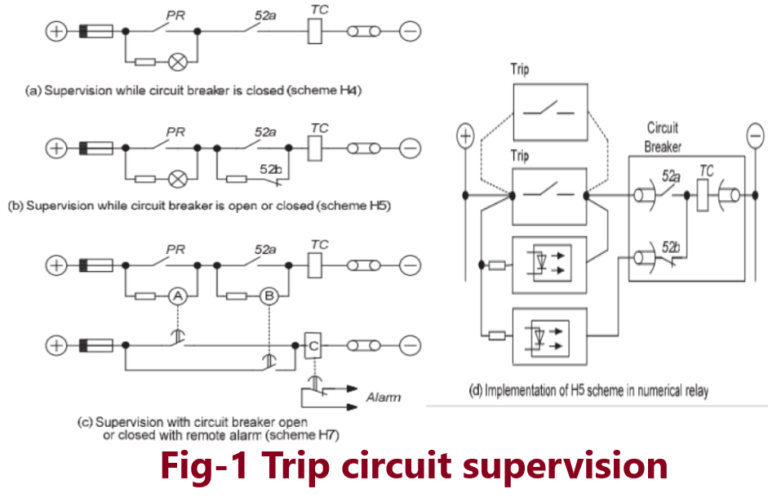
The trip circuit includes the protection relay and other components, such as fuses, links, relay contacts, auxiliary switch contacts, etc., and in some cases through a considerable amount of circuit wiring with intermediate terminal boards. These interconnections, coupled with the importance of the circuit, result in a requirement in many cases to monitor the integrity of the circuit. This is known as trip circuit supervision. The simplest arrangement contains a healthy trip lamp or LED, as shown in Figure-1(a).
The resistance in series with the lamp prevents the breaker being tripped by an internal short circuit caused by failure of the lamp. This provides supervision while the circuit breaker is closed; a simple extension gives pre-closing supervision.
Figure 1(b) shows how, the addition of a normally closed auxiliary switch and a resistance unit can provide supervision while the breaker is both open and closed.
In either case, the addition of a normally open push-button contact in series with the lamp will make the supervision indication available only when required.
Schemes using a lamp to indicate continuity are suitable for locally controlled installations, but when control is exercised from a distance it is necessary to use a relay system. Figure-2(c) illustrates such a scheme, which is applicable wherever a remote signal is required.
With the circuit healthy either or both of relays A and B are operated and energise relay C. Both A and B must reset to allow C to drop-off. Relays A, B and C are time delayed to prevent spurious alarms during tripping or closing operations. The resistors are mounted separately from the relays and their values are chosen such that if any one component is inadvertently short-circuited, tripping will not take place.
The alarm supply should be independent of the tripping supply so that indication will be obtained in case of failure of the tripping supply.
The above schemes are commonly known as the H4, H5 and H7 schemes, arising from the diagram references of the utility specification in which they originally appeared. Figure 1(d) shows implementation of scheme H5 using the facilities of a modern numerical relay. Remote indication is achieved through use of programmable logic and additional auxiliary outputs available in the protection relay.
Pingback: Switch onto Fault (SOTF) Logic