What is Sag (dips) in Power quality?
A sag is a decrease to between 0.1 and 0.9 pu in rms voltage or current at the power frequency for durations from 0.5 cycle to 1 min. The power quality community has used the term sag for many years to describe a short-duration voltage decrease. Although the term has not been formally defined, it has been increasingly accepted and used by utilities, manufacturers, and end users.
The IEC definition for this phenomenon is dip. The two terms are considered interchangeable, with sag being the preferred synonym in the U.S. power quality community. Terminology used to describe the magnitude of a voltage sag is often confusing. A “20 percent sag” can refer to a sag which results in a voltage of 0.8 or 0.2 pu.
The preferred terminology would be one that leaves no doubt as to the resulting voltage level: “a sag to 0.8 pu” or “a sag whose magnitude was 20 percent.” When not specified otherwise, a 20 percent sag will be considered an event during which the rms voltage decreased by 20 percent to 0.8 pu. The nominal, or base, voltage level should also be specified. Voltage sags are usually associated with system faults but can also be caused by energization of heavy loads or starting of large motors.

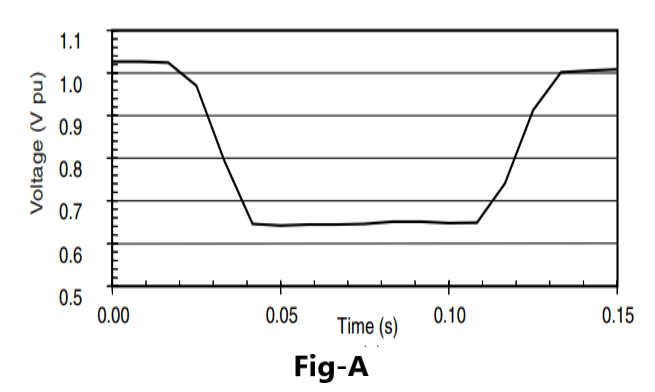
Figure-A shows a typical voltage sag that can be associated with a single-line-to-ground (SLG) fault on another feeder from the same substation. An 80 percent sag exists for about 3 cycles until the substation breaker is able to interrupt the fault current. Typical fault clearing times range from 3 to 30 cycles, depending on the fault current magnitude and the type of overcurrent protection.
An induction motor will draw 6 to 10 times its full load current during start-up. If the current magnitude is large relative to the available fault current in the system at that point, the resulting voltage sag can be significant. In this case, the voltage sags immediately to 80 percent and then gradually returns to normal in about 3 s. Note the difference in time frame between this and sags due to utility system faults.
Until recent efforts, the duration of sag events has not been clearly defined. Typical sag duration is defined in some publications as ranging from 2 ms (about one-tenth of a cycle) to a couple of minutes. Undervoltages that last less than one-half cycle cannot be characterized effectively by a change in the rms value of the fundamental frequency value. Therefore, these events are considered transients.
Undervoltages that last longer than 1 min can typically be controlled by voltage regulation equipment and may be associated with causes other than system faults. Therefore, these are classified as long-duration variations.
Sag durations are subdivided here into three categoriesinstantaneous, momentary, and temporary, which coincide with the three categories of interruptions and swells. These durations are intended to correspond to typical utility protective device operation times as well as duration divisions recommended by international technical organizations.
What is Swell in power quality?

A swell is defined as an increase to between 1.1 and 1.8 pu in rms voltage or current at the power frequency for durations from 0.5 cycle to 1 min. As with sags, swells are usually associated with system fault conditions, but they are not as common as voltage sags. One way that a swell can occur is from the temporary voltage rise on the unfaulted phases during an SLG fault.
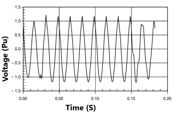
Figure-B illustrates a voltage swell caused by an SLG fault. Swells can also be caused by switching off a large load or energizing a large capacitor bank. Swells are characterized by their magnitude (rms value) and duration.
The severity of a voltage swell during a fault condition is a function of the fault location, system impedance, and grounding. On an ungrounded system, with an infinite zero-sequence impedance, the line-to-ground voltages on the ungrounded phases will be 1.73 pu during an SLG fault condition.
Close to the substation on a grounded system, there will be little or no voltage rise on the unfaulted phases because the substation transformer is usually connected delta-wye, providing a low-impedance zero-sequence path for the fault current. Faults at different points along four-wire, multigrounded feeders will have varying degrees of voltage swells on the unfaulted phases.
The term momentary overvoltage is used by many writers as a synonym for the term swell.
