
Table of Contents
ToggleWhat is Switchgear ?
The apparatus used for switching, controlling and protecting the electrical circuits and equipment is known as switchgear.
The switchgear equipment is essentially concerned with switching and interrupting currents either under normal or abnormal operating conditions. The tumbler switch with ordinary fuse is the simplest form of switchgear and is used to control and protect lights and other equipment in homes, offices etc.
For circuits of higher rating, a high-rupturing capacity (H.R.C.) fuse in conjuction with a switch may serve the purpose of controlling and protecting the circuit. However, such a switchgear cannot be used profitably on high voltage system (3·3 kV) for two reasons.
Firstly, when a fuse blows, it takes some time to replace it and consequently there is interruption of service to the customers. Secondly, the fuse cannot successfully interrupt large fault currents that result from the faults on high voltage system. With the advancement of power system, lines and other equipments operate at high voltages and carry large currents.
When a short circuit occurs on the system, heavy current flowing through the equipment may cause considerable damage. In order to interrupt such heavy fault currents, automatic circuit breakers (or simply circuit breakers) are used. A circuit breaker is a switchgear which can open or close an electrical circuit under both normal and abnormal conditions. Even in instances where a fuse is adequate, as regards to breaking capacity, a circuit breaker may be preferable. It is because a circuit breaker can close circuits, as well as break them without replacement and thus has wider range of use altogether than a fuse.
Essential features of switchgear
The essential features of switchgear are :
(i) Complete reliability. With the continued trend of interconnection and the increasing capacity of generating stations, the need for a reliable switchgear has become of paramount importance. This is not surprising because switchgear is added to the power system to improve the reliability. When fault occurs on any part of the power system, the switchgear must operate to isolate the faulty section from the remain circuit.
(ii) Absolutely certain discrimination. When fault occurs on any section of the power system, the switchgear must be able to discriminate between the faulty section and the healthy section. It should isolate the faulty section from the system without affecting the healthy section. This will ensure continuity of supply.
(iii) Quick operation. When fault occurs on any part of the power system, the switchgear must operate quickly so that no damage is done to generators, transformers and other equipment by the short-circuit currents. If fault is not cleared by switchgear quickly, it is likely to spread into healthy parts, thus endangering complete shutdown of the system.
(iv) Provision for manual control. A switchgear must have provision for manual control. In case the electrical (or electronics) control fails, the necessary operation can be carried out through manual control.
(v) Provision for instruments. There must be provision for instruments which may be required. These may be in the form of ammeter or voltmeter on the unit itself or the necessary current and voltage transformers for connecting to the main switchboard or a separate instrument panel.
Switchgear equipment
Switchgear covers a wide range of equipment concerned with switching and interrupting currents under both normal and abnormal conditions. It includes switches, fuses, circuit breakers, relays and other equipment. A brief account of these devices is given below. However, the reader may find the detailed discussion on them in the subsequent chapters.
Switches
A switch is a device which is used to open or close an electrical circuit in a convenient way. It can be used under full-load or no-load conditions but it cannot interrupt the fault currents. When the contacts of a switch are opened, an *arc is produced in the air between the contacts. This is particularly true for circuits of high voltage and large current capacity. The switches may be classified into (i) air switches (ii) oil switches. The contacts of the former are opened in air and that of the latter are opened in oil.
Air-break switch
It is an air switch and is designed to open a circuit under load. In order to quench the arc that occurs on opening such a switch, special arcing horns are provided. Arcing horns are pieces of metals between which arc is formed during opening operation. As the switch opens, these horns are spread farther and farther apart. Consequently, the arc is lengthened, cooled and interrupted. Air-break switches are generally used outdoor for circuits of medium capacity such as lines supplying an industrial load from a main transmission line or feeder.
Isolator or disconnecting switch.
It is essentially a knife switch and is designed to open a circuit under noload. Its main purpose is to isolate one portion of the circuit from the other and is not intended to be opened while current is flowing in the line. Such switches are generally used on both sides of circuit breakers in order that repairs and replacement of circuit breakers can be made without any danger. They should never be opened until the circuit breaker in the same circuit has been opened and should always be closed before the circuit breaker is closed.
Oil switches.
As the name implies, the contacts of such switches are opened under oil, usually transformer oil. The effect of oil is to cool and quench the arc that tends to form when the circuit is opened. These switches are used for circuits of high voltage and large current carrying capacities.
Fuses
A fuse is a short piece of wire or thin strip which melts when excessive current flows through it for sufficient time. It is inserted in series with the circuit to be protected. Under normal operating conditions, the fuse element it at a temperature below its melting point. Therefore, it carries the normal load current without overheating. However, when a short circuit or overload occurs, the current through the fuse element increases beyond its rated capacity. This raises the temperature and the fuse element melts (or blows out), disconnecting the circuit protected by it. In this way, a fuse protects the machines and equipment from damage due to excessive currents. It is worthwhile to note that a fuse performs both detection and interruption functions.
Circuit breakers
A circuit breaker is an equipment which can open or close a circuit under all conditions viz. no load, full load and fault conditions. It is so designed that it can be operated manually (or by remote control) under normal conditions and automatically under fault conditions. For the latter operation, a relay circuit is used with a circuit breaker. circuit breaker essentially consists of moving and fixed contacts enclosed in strong metal tank and immersed in oil, known as transformer oil. Under normal operating conditions, the contacts remain closed and the circuit breaker carries the full-load current continuously.
In this condition, the e.m.f. in the secondary winding of current transformer (C.T.) is insufficient to operate the trip coil of the breaker but the contacts can be opened (and hence the circuit can be opened) by manual or remote control. When a fault occurs, the resulting Over current in the C.T. primary winding increases the secondary e.m.f. This energises the trip coil of the breaker and moving contacts are pulled down, thus opening the contacts and hence the circuit. The arc produced during the opening operation is quenched by the oil. It is interesting to note that relay performs the function of detecting a fault whereas the circuit breaker does the actual circuit.
Relays
A relay is a device which detects the fault and supplies information to the breaker for circuit interruption. Fig Shows typical Relay circuit. It can be divided into three parts viz.
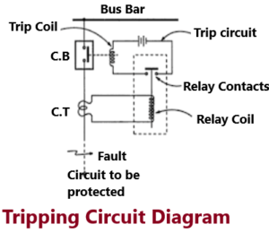
(i) The primary winding of a current transformer (C.T.) which is connected in series with the circuit to be protected. The primary winding often consists of the main conductor itself.
(ii) The second circuit is the secondary winding of C.T. connected to the relay operating coil.
(iii) The third circuit is the tripping circuit which consists of a source of supply, trip coil of circuit breaker and the relay stationary contacts. Under normal load conditions, the e.m.f. of the secondary winding of C.T. is small and the current flowing in the relay operating coil is insufficient to close the relay contacts. This keeps the trip coil of the circuit breaker un energised. Consequently, the contacts of the circuit breaker remain closed and it carries the normal load current. When a fault occurs, a large current flows through the primary of C.T. This increases the secondary e.m.f. and hence the current through the relay operating coil. The relay contacts are closed and the trip coil of the circuit breaker is energised to open the contacts of the circuit breaker.
Pingback: Role of Electrical engineer in Thermal Power Plant
Pingback: Role of Electrical Engineer in Construction