
Table of Contents
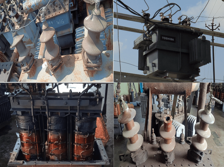
ToggleProbable Causes of DT (Distribution Transformer) failure
Insufficient Oil level
Improper oil level in the DTs due to poor maintenance, leakage and theft of oil as it causes temperature rise, hotspot leading to DT failure especially in rural areas
Due to leakage in transformer tank or radiator are the major causes for low oil level in transformer tank.
Blasting of transformer tank.
Low oil level can cause burning of Delta wire.
Oil theft in transformer can cause heavy damage to HV and LV winding of transformer.
Seepage of water in oil
Water ingression through improper sealing / damaged tank body causes loss of dielectric strength resulting to insulation failure. Mostly, the lower most HV coil gets affected due to water settling at the bottom of the tank.
Due to low oil level entrance of water through HV and LV studs.
Damage HV bushings.
Damage gaskets and rubber parts.
Damage conservator tank.
Missing of oil filling cap and Air release plug.
Arcing with tank.
Accumulation of water in base of conservator tank.
Due to moisture oxidation takes place. Oxidation results in the formation of acids in the insulating oil, which in turn, contributes to the formation of sludge.
Paper insulation deterioration since paper insulation has a great affinity for water.
Prolonged Pink Silica gel in breather
Missing of silica gel breather.
Exhausted silica gel in breather.
Decreases BDV value of transformer oil.
Causes damage to bottom coils of transformer after a prolong time period.
Prolonged Over loading
Transformer that experiences sustained loading that exceeds the name plate capacity often faces failure due to overloading
Transformer failure period depends on insulation capability of transformer.
Radiator cooling capability.
Heavy damage to core and winding of transformer.
Heavy carbonization of transformer oil.
Burning of Lead due to overloading.
Core insulation failure.
Insulation on all coils in all phases turned brittle
Single Phase and Unbalanced loading
Single phase LT line in village specially in tribal areas.
Running of single phase motor in agriculture field.
Zero phase sequence current caused by unbalance loads or faults in the system and causes unwanted heating.
Heavy carbonization of transformer oil.
Damage to core of transformer.
Poor Earthing
Improper earthing is one of the main reason casing unbalanced voltages, floating neutral and causing DT failure.
Use of GI wire for neutral earthing in village and urban areas.
Faulty Termination (Improper sized lugs etc)
Unnecessary increasing temperature of winding.
Damage to LV/HV metal parts and oil seal.
Creating un equal voltage on LV side.
Damages Delta/Jumper of HV winding.
Opening of connection due to overheating of joints.
The local heating generated by improper joints or connections may slowly lead to a deterioration of the oil if the joints are oil immersed.
Prolonged Short Circuit
End coils of transformers are damaged if short circuit fault is not clear by protecting device.
Improper Size of fuses
No use of MCB on LT side of DTs and using improper size of the fuses (for ease by maintenance staff)is another major reason for failure of DTs and affecting the safety of DTs and public life.
Usage of Aluminum wire strand in DO fuse.
In quite a few cases, it has been found that the protection system on both the HT and LT sides are usually absent from site or if present then they are bypassed. In some cases, this is deliberately done by the maintenance staff since they are troubled by multiple trippings.
Damage Bushings
Dust & dirt deposition, salt or chemical deposition, cement or acid fumes depositions on bushing.
Crack on bushing surface.
Continuous operation of flashed bushing.
Non cleaning of bushing in pre monsoon maintenance activity.
Low oil level.
Core Failure
Use of high loss core leads to melting of varnish and short circuit between laminations, further increasing the losses.
Another very common cause of failure is due to lightening impulse/ surges.
Apart from this there are certain manufacturing defects like zigzag placing of coil spacers, use of poor grade of conductor, winding of coils with insufficient pressure etc. that may lead to failure in the long run. Ingression of external entities through explosion vent, falling of rust particles from rusted conservator tops etc. might also lead to failure.
Manufacturing Side Defects
Design/Manufacturing Errors/conditions such as loose or unsupported leads, loose blocking, poor brazing, poor joints in the intra winding leading to hotspot and insulation damage, inadequate core insulation, inferior short circuit strength, and foreign objects left in the tank.
Failure caused by Raw Material, Moisture in insulated paper, Sharp edge of low voltage winding, Assembly of tap changer, Loose winding connection, Thickness of transformer tank or lifting measure.
Improper brazing at coil/tap connections leads to hotspot. Failure in such cases is localized with melted aluminium.
Failure after repeated fault in LT feeder
Analysis of Failure DT (Distribution Transformer)
Sr No | Found damage during Inspection | Cause of Failure |
1 | Top coils in all 3phase got charred and all coils below them are O.K | Low oil level |
2 | Internal Jumpers got cut | Bad soldering and /or surge |
3 | End coils got damaged | Severe external short circuit not cleared by fuses in time |
4 | Insulation on all coils in all phases turned brittle | Obvious case of continuous overloading |
5 | Inter turn short | Poor insulation due to: Ageing, Bad oil, Moisture, Continuous overloading etc. |
6 | Damage of turns of coils | Poor insulation due to: Ageing, Bad oil, Moisture, Continuous overloading etc. |
7 | Strips forming L.V star point got sheared | Unbalance in loading coupled with bad earthing. |
8 | L.T Coil damages | Insulation failure on L.T: repeated test charges on fault |
9 | Moisture inside transformer | Bad breather maintenance, loose top gaskets, puncture on vent pipe diaphragm |
10 | High magnetizing current and flash to core | Core bolt insulation failure |
Case study of Failure DT (Distribution Transformer)
Case Study | Observation found at testing | Cause of defect | Rectification and step to avoid failure |
Un equal voltages. Continuity not found with the “B” Phase HT. | HT lead in “B” bushing rod, came out. | The lead was tight. Hence came out from Rod. | Flexibility of connection increased and soldered with Rod. |
HG Fuse blown out. IR value and continuity OK. | “B” Phase coil inter-turn short in 2nd stack. No shattering of coils | Insulation failure due to ageing. Since no earth contact of winding, I.R. values are OK. | Failed stack replaced and sent for use. |
Oil Sample not satisfactory in 3 consecutive tests. | Found heavy sludge & moisture absorption I.R. Value low. Found vent pipe diaphragm broken. Gauge glass broken. Breather all right. | Sludge due to ageing, water entry through vent pipe & gauge glass | Oil completely discarded. Core and coil cleaned. Dried in chamber. Put hot oil circulation with new oil and tested OK. |
HG Fuse blowing out on load.(Attended at site) | Oil Level found up to core level only. Gauge glass showing OK | Gauge Glass indication misleading. Actually oil level is low. HT Lead insulation charred due to heat. Coil alright. | Gauge Glass cleaned. Block in air hole removed. Insulation of leads strengthened. Transformer put back in service-OK. |
HG Fuse frequently blows out in “B” Phase | Insulation of lead inside “B” Phase Bushing found charred. All coils in Good condition | Insulation of lead inside “B” Phase Bushing found charred. All coils in Good condition. | Advised the field to release air monthly from tank. Charred insulation replaced and sent for use. |
HG Fuse in all 3 phases blown out. | Inter turn short in R Phase – 3rd stack. Y Phase – 4th stack B Phase – 2nd & 3rd stack | Suspected heavy absorption of moisture. Oil sample not satisfactory. Crackle test proved positive. | All good stacks removed. Core with LT coil placed in Hot Air Chamber and dried. Failed coils replaced. Put into use after circulation and test. |
All 3 HG Fuses blow out slowly after 1Hour (Examined at Field) | HT Leads insulation near top of bushing found charred | Conservator Oil level below bushing rod. Absence of oil around caused heating of leads | Insulation Sleeves changed. Higher oil level was asked to be maintained. |
Oil spurt out (Similar happening on previous transformers also) | B Phase end windings (Top and Bottom found shattered) | Lightning surges entered and caused shattering. (Area prone for lightning) | Coil rewound and sent. The previous failure was also in same “B” Phase. Asked to examine HT LA of “B” Phase. All three LAs changed and no such failure thereafter. |
LT Voltage – Ok. But Load in “R” Phase could not be loaded. | LT & HT connection found alright. No visual defect. SC test revealed no current in R Phase, full current in neutral. | Examined the soldered connections in “R” Phase and found “R” Phase bottom delta connection improper. (not completely cut) | Defective connections resoldered and found OK. Improper soldering gave way during use. |
Undue heating in LT Rod. “R” Ph. Rod worn out and Insulation tape charred. | “R” Phase rod inside connection loosened | Connection loosened due to improper handling of bushing during jumper connections. | Connections tightened and sent for use. Advised to use check nuts and proper handling. |
L. T. Voltage Measured – Ok. But found drop in voltage when load is connected | Neutral Bushing Connection loosened inside. | Improper handling of neutral bushing during meggering | Neutral Connection set right and sent for use. Advised to handle bushing connections properly. |
Pingback: Types of Distribution Transformer - Electricalsphere
Loving the info on this site, you have done great job on the blog posts.