
Auto changeover of Motor in Industries
Induction motors are often used to drive critical loads. In some industrial applications, such as those involving the pumping of fluids and gases, this has led to the need for a power supply control scheme in which motor and other loads are transferred automatically on loss of the normal supply to an alternative supply.
A quick changeover, enabling the motor load to be re-accelerated, reduces the possibility of a process trip occurring. Such schemes are commonly applied for large generating units to transfer unit loads from the unit transformer to the station supply/start-up transformer.
When the normal supply fails, induction motors that remain connected to the busbar slow down and the trapped rotor flux generates a residual voltage that decays exponentially. All motors connected to a busbar will tend to decelerate at the same rate when the supply is lost if they remain connected to the busbar.
This is because the motors will exchange energy between themselves, so that they tend to stay ‘synchronised’ to each other. As a result, the residual voltages of all the motors decay at nearly the same rate. The magnitude of this voltage and its phase displacement with respect to the healthy alternative supply voltage is a function of time and the speed of the motors.
The angular displacement between the residual motor voltage and the incoming voltage will be 180° at some instant. If the healthy alternative supply is switched on to motors which are running down under these conditions, very high inrush currents may result, producing stresses which could be of sufficient magnitude to cause mechanical damage, as well as a severe dip in the alternative supply voltage.
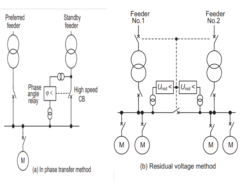
Two methods of automatic transfer are used:
- In-phase transfer system
- Residual voltage system
The in-phase transfer method is shown in Figure-A. Normal and standby feeders from the same power source are used. Phase angle measurement is used to sense the relative phase angle between the standby feeder voltage and the motor busbar voltage.
When the voltages are approximately in phase, or just prior to this condition through prediction, a high speed circuit breaker is used to complete the transfer. This method is restricted to large high inertia drives where the gradual run down characteristic upon loss of normal feeder supply can be predicted accurately.
Figure-B shows the residual voltage method, which is more common, especially in the petrochemical industry.
Two feeders are used, supplying two busbar sections connected by a normally open bus section breaker. Each feeder is capable of carrying the total busbar load. Each bus section voltage is monitored and loss of supply on either section causes the relevant incomer CB to open.
Provided there are no protection operations to indicate the presence of a busbar fault, the bus section breaker is closed automatically to restore the supply to the unpowered section of busbar after the residual voltage generated by the motors running down on that section has fallen to a an acceptable level.
This is between 25% and 40%, of nominal voltage, dependent on the characteristics of the power system. The choice of residual voltage setting will influence the re-acceleration current after the bus section breaker closes. For example, a setting of 25% may be expected to result in an inrush current of around 125% of the starting current at full voltage. Alternatively, a time delay could be used as a substitute for residual voltage measurement, which would be set with knowledge of the plant to ensure that the residual voltage would have decayed sufficiently before transfer is initiated.
The protection relay settings for the switchboard must take account of the total load current and the voltage dip during the re-acceleration period in order to avoid spurious tripping during this time. This time can be several seconds where large inertia HV drives are involved.