
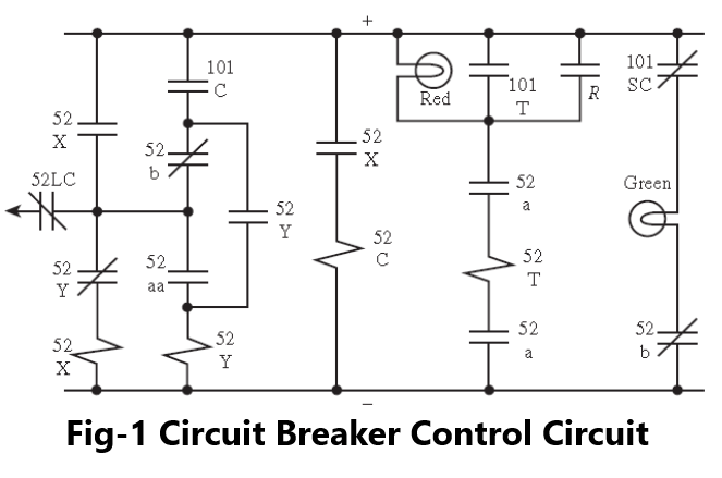
Consider the control circuit of circuit breaker shown in Figure 1, which is a complete tripping and closing circuit for a circuit breaker. Here, the protective relay contacts are shown as a single contact labeled “R” and this should be understood to include as many contacts as are actually available from the various relays at a given installation.
This control circuit, which is often called the X–Y control scheme, is designed to provide several unique safeguards, as follows:
The control is electrically trip free.
The control includes an anti-pumping feature.
A provision for reclosing is provided.
First, we examine the general concepts of the control scheme. Then we shall examine the above special features. Contacts in Figure 1 labeled 101 are manual control switches. There are three of these switches:
101C. Manual closing contact
101T. Manual tripping contact
101SC. Manual slip contact
Understand Control Circuit of Circuit breaker
First, assume that the circuit breaker is open, and the green light is on, indicating the open status. The operator now wishes to manually close the breaker. This is accomplished by manually closing contact 101C. Since the breaker is initially open, contacts 52a and 52aa are both open. Similarly, contacts 52b are closed. Closing 101C momentarily energizes coils 52X since 52Y “b” contacts are closed. Coil 52X picks up its respective contacts in the close circuit causing current to flow through the circuit breaker closing coil 52C, thereby closing the circuit breaker. Another 52X contact (to the left of 101C) seals in the closing contact 101C.
Now, when the breaker main contacts close, the 52 auxiliary contacts change their open/close status. Thus, 52aa closes, which picks up coil 52Y, thereby opening the 52X coil and de-energizing the closing coil 52C.Note that 52b opens, which assures that the 101C circuit remains open. Contact 52Y is used for anti-pumping and is discussed below. Thus, by momentarily depressing 101C, the operator puts in motion a number of control features. The end result is that the breaker is closed, the red light is on and the green light is off. The lamp current flows through 52T, but the current magnitude is much too small to operate the breaker.
To manually trip the breaker, the operator closes contacts 101T, which causes current to flow through the trip coil 52T, thereby tripping the circuit breaker, turning off the red light, and energizing the green light.
Now, suppose the operator manually closes 101C and closes the breaker when there is a permanent fault on the line. Moreover, suppose the operator stubbornly holds the 101C contacts closed. Should this occur, the first reaction after closing will be the pick-up of the relay contacts because of the fault, which trips the breaker. However, the initial breaker closure also picks up 52aa. This energizes coil 52Y, the anti-pumping coil, which is held closed by contacts 52Y as long as 101C is depressed. At the same time, coil 52Y also opens the circuit of closing auxiliary coil 52X, preventing further closing of the breaker. Thus, the breaker is closed, but opens immediately and remains open, even if the operator holds 101C in the closed position.
The reclosing feature uses contact 52LC, a latching contact, not shown in Figure 1. After the breaker is tripped, the mechanical breaker closing mechanism is latched to permit closing. This breaker action closes contacts 52LC. These contacts can be connected to a reclosing relay, which can apply positive potential to coil 52X, initiating the automatic reclosure of the line.
Note that it is essential that the trip circuit be energized from the battery supply, since the ac line or bus voltage may be badly depressed during a fault condition. The breaker closing voltage may be supplied from the ac bus, however. In this case, the control circuit is the same except that 52X, 52Y, and 52C are connected to an ac supply. In the case of dc closing supply, the dc may be supplied as part of the tripping dc as shown in Figure 1. Alternatively, closing dc supply may be arranged through a separately fused supply connected downstream of the tripping dc circuit. In such arrangements, the breaker cannot be closed unless the tripping dc supply is also established.
Really fantastic visual appeal on this internet site, I’d value it 10 10.