
Table of Contents
ToggleDefinition of Current Transformer
Current Transformer (CT) are used for reducing / stepping down ac current from higher value to lower value for measurement / protection / control. Typical secondary current is 5 A rms . CT secondary current is substantially proportional to primary current and differs in phase from it by ideally zero degree.
Working Principle of Current Transformer
A Current Transformer (CT) functions with same basic working principle of electrical power transformer but here is some difference. If a electrical power transformer or other general purpose transformer, primary current varies with load or secondary current.
In case of CT, primary current is system current and thisn primary current or system current transforms to CT secondary, hence secondary current or burden current depends upon primary current of current transformer.
In a power transformer , if load is disconnected, only magnetizing current flows in primary. Primary of power transformer takes current from source proportional to load connected with secondary .
In CT, primary is connected in series with power line. So current through its primary is current flowing in power line and does not depend upon whether load or burden is connected to secondary or not or what is impedance value of burden.
CT has very few turns in primary where as secondary turns is large in number. Say NP is number of turns in CT primary and IP is current through primary. Hence primary AT is equal to NP IP AT. If number of turns in secondary and secondary current are NS and IS respectively then Secondary AT is equal to NS IS AT.
In an ideal CT , primary AT magnitude= secondary AT magnitude. So if a CT has one turn in primary and 400 turns in secondary winding, and if it has 400 A current in primary then it will have 1A in secondary . and turn ratio of CT will be 400/1A.
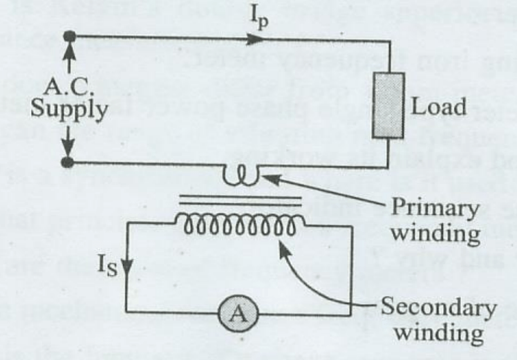
The primary winding of CT is connected in series with line in which current is to be measured and secondary is connected to ammeter.
Types of Current Transformer

There are two types of current transformers:
- Wound primary type
- Bar primary type
Wound primary is used for smaller currents, low fault level installations due to thermal limitations.
Bar primary is used for currents more than 100 A . Protection CTs are most frequently of bar primary, toroidal core with evenly distributed secondary winding type construction. In such CTs, secondary winding can be conveniently put inside high voltage bushings.
As per Application of core, There are three types of CTs
1.Measuring CTs
2.Protection CTs
3.Protection CTs for special applications
Core of Current Transformer
CT core is made of continuously wound strip of magnetic material. Primary conductor passes through eye of ring. Secondary is wound on core , turns ratio N2/N1 is very high so that I1 /I2 is very high.
Ring type core is commonly used when primary current is large. Secondary winding is distributed round ring and primary winding is a single bar. It is a jointless core and there is very small leakage reactance.
Burden of Current Transformer
In current transformer, secondary winding has a very small impedance or “Burden” , so current transformer operates on short circuit conditions. Rated burden of CT is maximum load in volt- amperes which may be applied across secondary terminals without ratio and phase angle errors exceeding permissible limits.
Burden depends upon number of instruments or relays connected and their individual burdens. Burden may be expressed as: 0.5 ohm impedance or 12.5 VA at 5 amperes. Let rated burden B volt amperes at rated current Is amp.
Then ohmic impedance burden Zb = B/I2 ohms
if CT is to feed an indicating meter 1.0VA, a record watt meter 5VA , an o/c relay 6VA . Total burden =12VA If resistance of connecting leads is 0.2 ohm , its burden = I2R = 5VA then total burden on CT = 17VA.
Terms regarding Current Transformer
Rated primary current: value of primary current on which primary performance of CT is specified . Rated primary current is assigned after conducting heat run tests.
Rated short time current(primary) : r.m.s value of a.c. component which CT can carry for rated time without damage due to thermal or electro-dynamic stresses.
Rated secondary current: value of secondary current , marked on rating plate.
Current error or ratio error: %age error in magnitude of secondary current is defined in terms of current error.
Phase angle error: phase angle between primary current vector and reversed secondary current vector
Accuracy class: class assigned to CT with specified limits of ratio error and phase angle error
Over current factor: ratio of rated short time current to rated primary current
Insulation level (primary) : insulation level of CT refers to withstand values of power frequency withstand voltage and impulse withstand voltage.
Why Current Transformer never operate on Secondary open circuit condition?
CTs generally work at a low flux density. Core is made of very good metal to give small magnetizing current. On open-circuit, secondary impedance becomes infinite and core saturates. This induces a very high voltage in primary up to approximately system volts and corresponding volts in secondary will depend on number of turns ,multiplying up by ratio i.e.volts/turn ×no. of turns).
Since CT has much more turns in secondary compared to primary, voltage generated on open-circuited CT will be much more than system volts, leading to flashovers. Hence, current transformer must never be operated on open- circuit.
Current Transformer Core connection
Secondary windings of different phases of Current Transformers are generally star connected. A typical wiring connection for Core – 1 of Current Transformers in the Bay Marshalling Kiosk / Junction Box. Shown in Figure.

Knee Point Voltage of Current Transformer
The magnetizing characteristic of a CT is a plot between the secondary applied voltage and the corresponding magnetizing current taken by the CT.
It is the voltage on the secondary excitation characteristic beyond which a 10 % increase in secondary EMF, would cause 50% increase in exciting current.
Pingback: 11kV/400V Pole mounted sub-station
Pingback: Red-HOT on CT Pad Clamp in Electrical substation
Pingback: Zero IR value of CT at Substation
Pingback: Working of Translay Relay
Thank you for sharing your info. I truly appreciate your efforts and I
am waiting for your further post thank you once again.
Thanks for appreciation.
For more electrical Knowledge, Please follow my Insta/Telegram/Whatsapp group.
Now, my focus on spread my website content to more readers.
To boost my moral, Please share my website to your friends.
Pingback: Frequent Tripping of feeder on earth fault after faulty CT replacement
Pingback: Optical Current Transducers: Working, Types and Advantage
Pingback: How to find out the knee point voltage of Current Transformer - Electricalsphere
Enjoyed looking at this, very good stuff, regards.
Great tremendous things here. I?¦m very satisfied to look your article. Thanks so much and i’m looking forward to contact you. Will you please drop me a e-mail?