Working of Translay Relay

Translay relay is a voltage balanced system in which the secondary CT voltages (voltages are proportional to the CT secondary current as air-cored CTs are used) at the ends of the feeder are compared. The CTs are connected in opposition (see Fig.1). Associated with the CT at each end is an induction relay. The upper magnet system acts as a quadrature transformer and produces at the pilot terminals a voltage which varies with the primary current.
As long as the currents at the two ends are equal, the voltages induced are also equal and hence no current flows in the pilot wires. In case the CTs are of ordinary instrument type where there is possibility of dissymmetry in the characteristics of the CTs at the two ends, compensating devices are provided in the relay to neutralize the effect of unbalancing of the CTs.
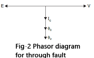

In case of a through fault or due to asymmetry in CTs under normal conditions the current through the pilot wires is capacitive and, therefore, the flux in the series magnet (due to capacitive current) is in phase with the leakage flux from the upper magnet thereby the net torque on the disc is zero. This is shown in the phasor diagram (Fig. 2). Here V is the voltage across the CT secondary and E is the induced voltage across the pilot wires, jc the flux in the upper magnet, jc the flux in the lower magnet and Ic the pilot current.
Whenever an internal fault occurs, current flows through the pilot wires because either one of the voltages has reversed in polarity (if the feeder is fed from both the ends) or the voltage at one end has collapsed (if the feeder is fed from one end only). The relay at an end will operate if there is current in its upper and lower coils and it will not operate at an end with no primary current because there is current only in the lower coil. Under internal fault condition since the pilot wire impedance is mostly resistive, the current through the pilot wire will be in phase with the secondary voltage. The phasor diagram is shown in Fig. 3 for this condition. Since the two fluxes are 90° apart approximately, the positive torque is produced and the relay operates.

The copper loop fitted to the central limb of the upper electromagnet gives rise to the flux which when interacts with the pilot capacitance current prevents the operation of the relay as indicated by phasor diagram in Fig. 2. Bias is obtained by the action of a second copper loop, mounted on an outer limb of the upper magnet.
Under normal condition, when current flows in the upper coil only, the relay behaves as a shaded pole type but the torque produced is arranged to act in a reverse i.e., restraining sense. This feature is equivalent to providing restraining coil in a percentage differential relay and prevents the operation of the relay due to mismatching of the CTs and/or any spill current due to through faults. Translay relay protection when applied to 3-phase system requires a single relay element with a summation transformer as shown in Fig. 4.
The system needs only two pilot wires. The operation of the system is as follows:
Under normal condition since the system is balanced, there is no voltage induced in the secondary of upper electromagnet as the sum of three currents at any instant of time is zero. Even if there is any unbalanced loading of the phases, the unbalancing will induce voltage at both ends of the system and since the pilot wire connections are such that these voltages are in opposition and equal in magnitude, normally no current flows through the pilot wires. The operation further is exactly identical to the single phase system.
Summation current transformer is used whenever 3-phase currents at one end of the line are to be compared with currents at the other end of the line. The transformer gives single phase output, the magnitude of which depends upon the nature of fault. The arrangement is shown in Fig.4. For a balanced fault the current through cn of the winding is zero. The phase a current energizes 1 p.u. turns between a and b and the phasor sum of Ia and Ib flows in the 1 p.u. turns between b and c.