Advantages of D.C Transmission
Line Circuit: The line construction is simpler as compared to a.c. transmission. A single conductor line with ground as return can be compared with a 3-phase single circuit line. Hence the line is relatively cheaper and has the same reliability as that of a 3-phase single circuit line because 3-phase lines cannot operate, except for a short time when there is a single line to ground fault or a L-L fault as this creates unbalancing in the voltages and hence interfere with the communication lines and other sensitive apparatus on the system. It is claimed that a bipolar d.c. transmission line has the same reliability index as a two-circuit 3-phase line having six line conductors.
Power per Circuit: the power transmission capability of the bipolar line is same as that of the 3-phase single circuit line. The d.c. line is cheaper and simpler as it requires two conductors instead of three and hence 2/3 as many insulators, and the towers are cheaper and narrower and hence a narrow right of way could be used.
Power per Conductor: For transmitting power both on a.c. and d.c. circuits let us assume that the two lines have the same number of conductors and insulators. Assuming that the current is limited by temperature rise, the direct current equals the r.m.s. alternating current. Since the crest voltage in both cases is same for the insulators the direct voltage is 2 times the r.m.s. alternating voltage.
No Charging Current: In case of a.c. the charging current flows in the cable conductor, a severe decrease in the value of load current transmittable occurs if thermal rating is not to be exceeded; in the higher voltage range lengths of the order of 32 km create a need for drastic derating. A further current loading reduction is caused by the appreciable magnitude of dielectric losses at high voltages. Since in case of d.c. the charging current is totally absent the length of transmission is not limited and the cable need not be derated.
No Skin Effect: The a.c. resistance of a conductor is somewhat higher than its d.c. resistance because in case of a.c. the current is not uniformly distributed over the section of the conductor. The current density is higher on the outer section of the conductor as compared to the inner section. This is known as skin effect. As a result of this the conductor section is not utilized fully. This effect is absent in case of d.c.
No Compensation Required: Long distance a.c. power transmission is feasible only with the use of series and shunt compensation, applied at intervals along the line. For such lines shunt compensation (shunt reactors) is required to absorb the line charging kVAs during light load conditions and series compensation (use of series capacitors) for stability reasons. Since d.c. line operate at unity power factor and charging currents are absent no compensation is required.
Less Corona Loss and Radio Interference: The corona loss is directly proportional to(f + 25), where f is the frequency of supply. f being zero in case of d.c., the corona losses are less as compared to a.c. Corona loss and radio interference are directly related and hence radio interference in case of d.c. is less as compared to a.c. Also corona and radio interference slightly decrease by foul weather conditions (snow, rain or fog) in case of d.c. whereas they increase appreciably in case of a.c. supply.
Higher Operating Voltages Possible: The modern high voltage transmission lines a redesigned based on the expected switching surges rather than the lightning voltages because the former are more severe as compared to the latter. The level of switching surges due to d.c.is lower as compared to a.c. and hence, the same size of conductors and string insulators can be used for higher voltages in case of d.c. as compared to a.c. In cables, where the limiting factor is usually the normal working voltage the insulation will withstand a direct voltage higher than that of alternating voltage, which is already 1.4 times the r.m.s. value of the alternating voltage.
No Stability Problem: For a two machine system the power transmitted from one machine to another through a lossless system is given by
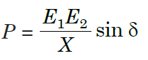
where X is the inductive reactance between the machines. The longer the length of the line, the higher is the value of X and hence lower will be the capability of the system to transmit power from one end to the other. With this the steady state stability limit of the system is reduced. The transient state stability limit is normally lower than the steady state; therefore with longer lines used for transmission, the transient stability also becomes very low. A d.c. transmission line does not have any stability problem in itself because d.c. operation is an asynchronous operation of the machines. In fact two separate a.c. systems interconnected only by a d.c. link do not operate in synchronism even if their nominal frequencies are equal and they can operate at different nominal frequencies e.g., one operating at 60 Hz and the other at50 Hz.
Low Short Circuit Currents: The interconnection of a.c. system through an a.c. system increases the fault level to the extent that sometimes the existing switchgear has to be replaced. However, the interconnection of a.c. system with d.c. links does not increase the level so much and is limited automatically by the grid control to twice its rated current. As a result of this fault d.c. links do not draw large currents from the a.c. system.