
Table of Contents
ToggleIntroduction
Earthing practices adopted at Generating Stations, Substations, Distribution structures and lines are of great importance. It is however observed that this item is most often neglected. The codes of practice, Technical Reference books, Handbooks contain a chapter on this subject but they are often skipped considering them as too elementary or even as unimportant. Many reference books on this subject are referred to and such of those points which are most important are compiled in the following paragraphs. These are of importance of every practicing Engineer in charge of Substations.
Importance of Earthing Practices
The earthing is provided for:
- a) Safety of Personnel
- b) Prevent or at least minimise damage to equipment as a result of flow of heavy fault currents.
- c) Improve reliability of Power supply
The earthing is broadly divided as:
- a) System earthing (Connection between part of plant in an operating system like LV neutral of a Power Transformer winding and earth).
- b) Equipment earthing (Safety grouding)
Connecting frames of equipment (like motor body, Transformer tank, Switch gear box, Operating rods of Air break switches, etc) to earth.
The system earthing and safety earthing are interconnected and therefore fault current flowing through system ground raises the potential of the safety ground and also causes steep potential gradient in and around the Substation.
But separating the two earthing systems have disadvantages like higher short circuit current, low current flows through relays and long distance to be covered to separate the two earths. After weighing the merits and demerits in each case, the common practice of common and solid (direct) grounding system designed for effective earthing and safe potential gradients is being adopted.
The earth resistance shall be as low as possible and shall not exceed the following limits:
Power Stations-0.5 Ohms, EHT Substations-1.0 Ohms, 33KV Stations-2.0 Ohms, D /t Structures-5.0 Ohms, Tower foot resistance-10.0 Ohms.
Step Potential
Step Potential is the difference in the voltage between two points which are one metre apart along the earth when ground currents flowing.
T ouch Potential
Touch Potential is the difference in voltage between the object touched and the ground point just below the person touching the object when ground currents are flowing.
Specification of Earthing
Depending on soil resistivity, the earth conductor (flats) shall be buried at the following depths.
Sr No | Soil Resistivity in ohms/metre | Economical depth of Burial in metres |
1 | 50-100 | 0.5 |
2 | 100-400 | 1.0 |
3 | 400-1000 | 1.5 |
To keep the earth resistance as low as possible in order to achieve safe step and touch voltages, an earth mat shall be buried at the above depths below ground and the mat shall be provided with grounding rods at suitable points. All non-current carrying parts at the Substation shall be connected to this grid so as to ensure that under fault conditions, none of these part are at a higher potential than the grounding grid.
Plate Earths
Taking all parameters into consideration, the size of plate earths are decided as:
Power Stations & EHT Station – Main- 100 x 16mm, Auxiliary- 50 x 8mm
Small Stations- 75 x 8mm
The complete specifications for providing earth mats at EHT & 33KV Substations, Distribution transformers & Consumers premises are reproduced below.
Earhing at EHT Substation
The earth mat shall be as per the approved layout. The earth mat shall be formed with the steel flats buried in the ground at a depth of 750mm on edge.
The earth mat shall extend over the entire switchyard as per the layout.
All the junctions of the steel flats while forming the earth mat and taking risers from the earth mat for giving earth connections to equipment, steel structures, conduits cable sheaths shall be properly welded. All joints shall be provided with suitable angle pieces for proper contact between flats.
Provisions shall be made for thermal expansion of the steel flats by giving smooth circular bends. Bending shall not cause any fatigue in the material at bends.
The earth mat shall be formed by welding 50×8 mm steel flat to the 100 x 16mm peripheral earth conductor. The grounding grid shall be spaced about 5 meters i.e in longitude and about 5 meters in the transverse directions. After the completion of earth mat, the earth resistance shall be measured. In case the earth resistance is more than one ohm the earth mat shall be extended by installing extra electrodes, so that the earth resistance is less than one ohm.
All fence corner posts and gate posts shall be connected to the ground by providing 32mm dia M.S rods of 3 metre length near the posts and connected to the main grounding mat.
All paint enamel and scale shall be removed from surface of contact on metal surface before making ground connection.
The risers taken along the main switchyard structures and equipment structures (upto their top) shall be clamped to the structures at an interval of not more than one metre.
50 x 8mm ground conductor shall be run in cable routes and shall be connected to the ground mat at an interval of 10 metres.
Grounding electrodes of 32mm dia 3mtr. long MS rods shall be provided at the peripheral corners of the earth mat. The grounding rods shall be driven into the ground and their tops shall be welded to clamp and the clamp together with the grounding rods shall be welded to the ground mat.
Lightening arrestors shall be provided with earth pits near them for earthing.
Cast iron pipes 125mm dia and 2.75 metres long and 9.5mm thick shall be buried vertically in the pits and a mixture of Bentonite compound with Black cotton soil a ratio of 1:6 is to be filled 300 mm dia and the pipe for the entire depth. Where it is not possible to go to a depth of 2.75 metres, 1.3 x 1.3 MMS plates, 25mm thick shall be buried vertically in pits of 2 metres depth and surrounded by Bentonite mixture atleast 2 metre away from any building or structure foundation. The plates shall be at least 15 metres apart. These earth pits in turn shall be connected to the earth mat.
Earthing at 33KV Substations
Providing of earth pit and earth matting include the following connected works:
- a) Excavation of earth pits of size 21/2ft x 21/2ft x 9ft in all type of soils.
- b) Providing of CI pipe of 3 inch diameter 9ft length with flange. All connections to CI pipe shall be with GI bolts and nuts.
- c) Filling of earth pit excavated with Bentonite with Black cotton soil (1:6) in alternate layers.
- d) Providing of cement collar of size 2ft diameter 2ft height 1 inch below the ground level.
- e) The top of the CI earth pipe should be at the surface level of the ground.
Providing of earth matting with MS flat 75 x 8mm including the following connected works:
- a) Excavation of trench in all types of soils of size 2½ ft depth and 1 ft. width.
- b) Laying of M.S flat 75 x 8mm in the excavated trench.
- c) Inter connecting all earth pits and welding properly at jointing location and junctions.
d) Back filling of earth completely.
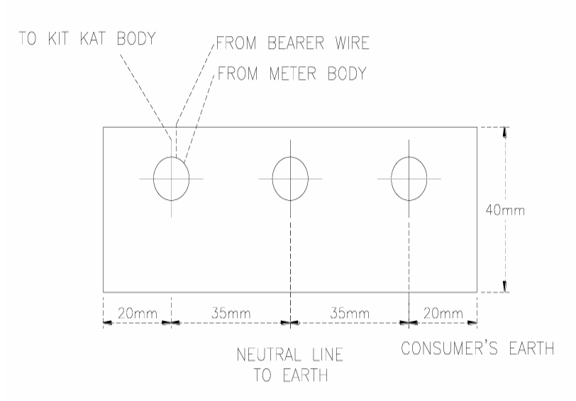
Earthing at Consumer’s premises
The earthing at Consumer’s premises shall be as per sketch below using a 6mm thick plate.
Earthing at D/P Structure
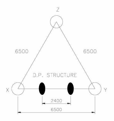
Three electrodes forming an equilateral triangle with minimum distance of 6500 mm, so that adequate earth buffer is available. Each Electrode shall be ‘A’ grade GI pipe of 2 inch thick and 8ft long and buried vertically so as to leave about 4 inch pipe length above ground level to fix a ‘U’ shaped clamp.
Note: The connections to the three earth conn.Electrodes should be as follows.
(A) To one of the earth electrodes on either side of double pole structure (X or Y)
i.One direct connection from three 11KV Lightening Arrestors.
ii.Another direct connection from the LT lightening Arrestors if provided.
(B)To each of the remaining two earth electrodes.
i.One separate connection from neutral (on the medium voltage side) of the Transformer (Two wires)
ii.One separate connection from the Transformer body and the handle of the 11KV A.B switch (Two separate body earths to tank)
iii.One separate connection from the Earthing Terminal of poles.
(C) 4mm G.I wire should be used for earth leads.
Tower line grounding
Ground rods are driven at the base of the tower. Where it is not feasible, an electrode is located within a distance of 200 ft. of the tower and grounding rods are provided at that point and tied to the tower base by a single buried wire.
If low resistance is not obtained with 200ft, crowfoot counterpoise with 4 wires is installed. The counterpoise conductors shall be 6 SWG galvanised steel wires taken away from the tower at mutually right angles and kept atleast 50ft apart. Each of these wires is terminated at a rod at the nearest point where low resistance is obtained. If counterpoise wires cannot be terminated within half span from the tower the wire is carried through a continuous counterpoise to the next tower, where the procedure is repeated.
Points of Earthing
Earth mat of 75 x 8 MS flat should be laid as outer of the switchyard compulsorily and see that the pole structures are enclosed in the outer mat.
Make vertical and horizontal sections for the outer mat as shown in the fig. The internal vertical and horizontal sections may be 75 x 8 or 50 x 6 MS flat.
The Earth mat should be laid minimum 600MM, below the ground level under the Earth mat and Bentonite powder is to be laid upto 25mm and over the earth mat. The same Bentonite compound with Black cotton soil a mixture of 1:6 ratio is to be placed upto 100 mm and the remaining earth trench is to be back filled with the soil.
See that each and every pole structure is earthed with 50 x 6 MS flat to the Earth Mat.
For every breaker there will be fine earth connections to the earth mat with 50 x 6 MS flat (a) Breaker body (b) Relay Panel (c) CT’s of the Breaker (d) and two sides of the breaker structure.
Lightening arrestor is to be connected one end directly to the earth mat and the other end is to the nearer earth pit or to the earth mat.
Line Isolators are to be connected directly to the earth mat.
The Power transformer body is to be connected two sides to the earth mat.
Twin neutral earthing should be done to Power Transformer as shown in the fig. one Earth flat of size 75 x 8mm M.S flat is directly connected to the earth pit and the earth pit is again connected to the Earth mat. The second neutral is directly connected to the earth mat,
Provide flexible jumpers thoroughly brazed as shown in figure
All AB switches operating rods are to be provided with coil earths and the AB switch support is to be earthed to the earth mat.
All the exposed earth flat which is dropping down from the breakers, CT’s structures should be applied with bituminous paint.
75 x 8 MS flat is to be laid around the control room from main earth and the panels of the breakers, midpoint of the Battery and Battery stand structures are to be earthed to the earth flat and make a section in front of the control room.
The distance between any two earth electrodes should be twice the length of the Electrode.
The cable (11 x 33KV) sheaths are to be earthed with 25 x 3 GI strip to the Earth mat.
The neutral of the station transformer is to be connected to the Earth mat directly with 25 x 3 GI strip. The body of the Station transformer two sides to be connected to the earth mat with 25 x 3 GI strip.
All the welding joints should be painted with bituminous paint.