A zigzag (earthing) transformer is a special purpose transformer. It has primary windings but no secondary winding. Earthing transformers are used to create a neutral point in a three phase system, which provides possibility for neutral earthing. The earthing can be through an arc-suppression reactor, a neutral earthing reactor or resistor or directly.
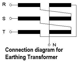
The design can be a transformer with just one winding, which is zigzag connected. The zero sequence impedance of such a winding is normally quite low, but it can be increased if the purpose is to limit the current through the transformer in case of an earth fault somewhere in the system. Consider a three-phase Y (wye) transformer with an earth connection on the neutral point. Cut each winding in the middle so that the winding splits into two. Turn the outer winding around and rejoin the outer winding to the next phase in the sequence (i.e. outer A phase connects to inner B phase, outer B phase connects to inner C phase, and outer C phase connects to inner A phase). This device is the zigzag transformer. Connection diagram for earthing transformer is shown in Figure.
During undisturbed system operation with balanced (symmetrical) voltages the current through the earthing transformer is small & of the same size as the magnetizing current. Unbalanced voltages will cause some higher currents flowing through the earthing transformer, which it must be capable to carry. An alternative connection to the zigzag is star/delta connection where the delta connected winding will compensate the zero sequence magnetic fields so it will be confined to a leakage field between the star and the delta winding and make the zero sequence impedance of the transformer relatively small. However, if it is desired to increase the zero sequence impedance, this can be achieved by opening the delta connection and insert a reactor or resistor.
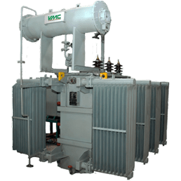
Earthing transformers are usually oil immersed and may be installed outdoor. In cases where a separate reactor is connected between the transformer neutral and earth, the reactor and the transformer can be incorporated in the same tank. When the earthing transformer is going to be used together with an arc-suppression reactor, the rated current (and its duration) of the earthing transformer will be determined by the data for the arc-suppression reactor. If the earthing transformer is used for directly earthing or through a current limiting reactor, the neutral current through the transformer will be high but the duration is limited to a few seconds. Earthing transformer must be designed to withstand the thermal and mechanical effects of the rated neutral current. The characteristic of earthing transformer should be selected to match the property of the system.
Most of the time in service the loading of earthing transformers is very low. It is the randomly occurring short . duration currents that cause any heating of significance. Ageing of the cellulose materials is then not a matter of concern. Regarding acceptable temperatures there are two aspects to consider. The temperature during currents of say 10 seconds duration must not cause softening of the winding conductor material, say 250oC for copper and 200oC for aluminium. For currents with duration in the order of hours or more, temperatures that cause excessive gas development in the oil should be avoided. Temperatures for items in direct contact with the oil should then not exceed 140oC.
The system earth fault protection relay may not be effective at low currents. To prevent damage to earthing transformer by such current, oil thermometer with alarm/trip contacts is recommended. Alternatively, the value of maximum continuous earth fault current may be declared and sensitive protection provided. The applicable standard for earthing transformers is IEC 60076-6.