
Electric power (Home) is usually generated at places which are far away from the places where it is consumed. At the generating station, the electric power is generated at 11,000 volts. This voltage alternates at a frequency of 50 Hz.
The power is transmitted over long distances at high voltage to minimise the loss of energy in the transmission.
Table of Contents
ToggleHome electrical wiring
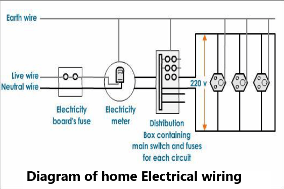
The electric power line enters our house through three wires- namely the live wire, the neutral wire and the earth wire. To avoid confusion we follow a colour code for insulating these wires. The red wire is the live wire, and the black wire is neutral. The earth wire is given green plastic insulation.
The live wire has a high potential of 220 volts whereas the neutral wire has zero potential. Thus the potential difference between the live wire and the neutral wire is 220-0 = 220 volts.
The earth wire is much thicker in size and is made of copper. One end of it is connected to a copper plate buried deep under the earth. The earth connection is made to the electric meter and then to the main switch.
In our homes, we receive supply of electric power through a main supply (mains), either supported through overhead electric poles or by underground cables.
The live wire and neutral wire, coming from the electric pole, enter a box fitted just outside our house which has a main fuse F1. The fuse is connected in series with the live wire. This is done so because it is only the live wire which has a high potential of 220 volts unlike the neutral wire which carries zero potential. The fuse F1 has a high rating of about 50 amperes. Thus it prevents any damage such as fire to the entire electrical wiring entering the house due to short-circuit or overloading.
The two wires then enter the electricity meter which records the electrical power consumed by us in kilowatt-hour (kWh). This meter is installed by the electric supply Department of our city.
These two wires coming out of the meter are then connected to a main switch which is placed in a distribution box. Another fuse F2 is placed in series with the live wire in this box for the sake of consumer safety.
There are two separate circuits in a house namely lighting circuit and power circuit. The lighting circuit with a 5 A fuse is used for running electric bulbs, fan, radio, TV, tube lights etc. and the power circuit with a 15 A fuse is used for running electric heater, electric iron, geyser, refrigerator etc as it draws more current.
The distribution circuits are always connected in parallel combination. In a parallel circuit even if there is a fault or short-circuiting in any one line, the corresponding fuse blows off leaving the other circuits and appliances intact and prevents damage to the entire house.
In case short-circuit occurs in the power circuit, then the power-fuse will blow off but our lights will continue to burn as the lighting circuit remains unaffected.
A constant voltage of the main line is available for all other electrical appliances.
Along with the two wires, a third wire called the earth wire also enters our house as shown in the fig. The earth connection is first made to the electric meter and then to the main switch. This wire then goes into the rooms along with the live and neutral wires
Requirements for Home electrical wiring
Cable and Earth sleeving.
Cable clips and or trunking (capping if the cables are to be buried in the wall).
Accessories (switches, sockets, Light fittings etc (if required).
Tools (Screw drivers, snips, hammer, drill).
Fixings (rawl plugs, screws, etc).
Socket or switch back boxes (‘Knockout’ boxes for mounting on walls, plastic boxes for mounting on walls).
Guidelines for better Home electrical wiring
Choosing the correct size cable for the job
Earthing
Basic light installation
Basic socket installation
Testing
Choosing the correct cable for the job
Choosing the correct size cable for a new electrical installation is crucial. The selection of an incorrectly rated cable could cause the cable to overheat, which may result in a fire.
This guide is not exhaustive, as the 16th Edition IEE wiring regulations stipulate in detail the correct cable sizes for specific installations, and cable lengths.
Situation cable to be used for | Recommended cable size | Recommended Fuse / MCB rating |
General Lighting | 1.0mm/1.5mm Twin+Earth | 5 / 6 amp |
General Power ring circuit | 2.5mm Twin Earth (x2) | 30 / 32 amp |
General Power radial circuit | 2.5mm Twin Earth | 15 / 16 amp |
Cookers upto 40 amps MAX load | 6.0mm Twin Earth | 30 / 40 amp |
Showers upto 9Kw | 6.0mm Twin Earth | 40 amp |
Earthing
Earthing forms an important part of the electrical system. All electrical apparatus fixed to the fabric of a property must have an earth connected to it, unless it has been specifically designed not to require one (the appliance you are installing will be ‘double insulated’ and will have a symbol which looks like 2 squares one inside the other, somewhere on its body).
The reason bonding is installed as detailed below, is to ensure all extraneous pipe work is at the same potential as earth. This is essentially so that in the event that a cable insulation fails or is damaged and it touches a pipe for instance, it will blow a fuse (or trip an MCB), rather than leaving the cable, and the pipe it is touching, LIVE!! Obviously this is quite dangerous.
Cross bonding
Kitchens and bathrooms should have all the copper pipe work joined together electrically with a 4mm earth cable. Bathrooms are a bit of a special subject, for full details refer to the IIE wiring regulations, but as a rule, ensure all apparatus ie, showers, shaver points etc.. Have their earths connected to the pipe work of the bathroom (using a 4mm earth cable). Strange as this may seem it is for your protection.
Main earth bonding
Gas, Oil and Water services must be connected via a 10mm earth cable to your main electrical earth for the building (usually connected to you distribution board).
Basic lighting installation
Lighting installations are generally run (in domestic installations) using twin and earth cables which are chased into the fabric of a building or run in mini-trunking over walls.
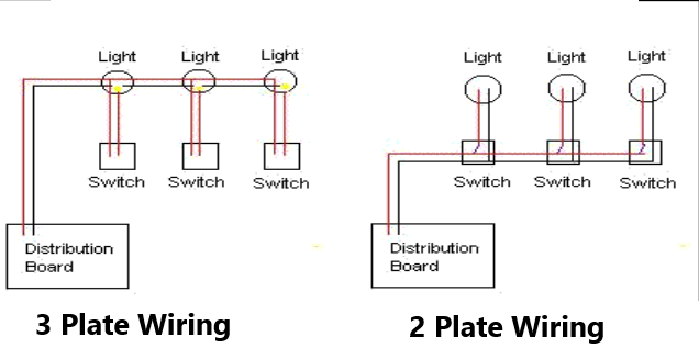
Lighting installed using twin and earth can be connected via three methods, 3-plate, 2-plate, and joint box. The 3-plate method is the most commonly used method in new properties today, as it is easy to install and maintain, I recommend where possible, utilizing this method, though when extending circuits for additional points, this is not always possible.
It is important that the earth cables are connected in all lighting circuits!
3-plate Method
The cables are taken from the distribution board (fuse board) to the nearest light, then another cable is linked from that light to the next and so on, until all lights on this circuit are linked together. Then each light that is to be switched separately has a switch wire taken from the light to the switch in that room. – (See 3-plate sketch below) .
2-plate Method
The cables are taken from the distribution board (fuse board) to the nearest switch, and then another cable is linked from that switch to the next and so on, until all switches on this circuit are linked together. Then from the switch a cable is run to the light that it will operate. – (See 2-plate sketch below).
Joint box method
This method consists of a supply taken from a local source (ie another light or distribution board) which is run to a joint box. The light and switch cables are also run to this joint box, and a supply to the next joint box (if required) also needs to be run from here. This method is only really useful on the extension of existing circuits, as it does take longer than either of the other two methods. Principally it works the same as the 3 plate method.
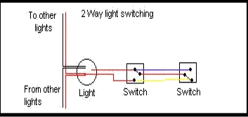
Switching
You can also switch one light from two locations using ‘2way’ switches. You will need a 3core + earth cable to complete this. There are several ways to do this, but for ease try to use this method. Install the three core and earth cable between the two switches you want to control the light with, ensuring one of the switches has already got a switch wire upto the light. (see 2way diagram below).
Basic socket installation
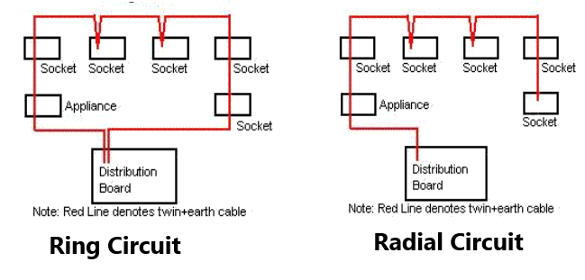
The electrical system for power installations is constructed using ‘ring’ and ‘radial’ circuits. Ring circuits have rules that must be adhered to, to prevent circuit overloading.
Ring Circuits
These circuits are comprised of a cable connected in a ring ( the cable comes from the distribution board, is run around an unlimited number of sockets before returning to the distribution board). It is important that the continuity of the ring is checked once the circuit is finished.
The principle of a ring circuit is it use two small cables to make one larger one. Ring circuits can have one cable spurred from it, but that cable must have only one socket on the end of it. These circuits, when run in a 2.5mm Twin and earth cable are generally rated at 32 amps MAX (see Sketch ‘Ring’ below)
Radial circuits
Radial circuits are one cable run from the distribution board to one or more sockets or appliances (ie. immersion heaters), and when run in 2.5mm twin and earth cable are rated at 16 amp. 4mm twin and earth cable or above could also be used, which would allow you to rate the cable at 32 amp. (see Sketch ‘Radial’ below)
Testing
It is a requirement of the IEE wiring regulations that any apparatus altered, or installed should be tested. It should also be noted that periodic inspections should also be executed regularly on the whole installation. Testing is outlined in another part of this site, but you will be required to have the appropriate test equipment to complete this. It is highly recommended that you have electrical apparatus inspected and tested (for domestic properties, these should be inspected at least every 5 years).
Rules & Regulations
Regulations to control the way in which domestic electrical installations are designed and installed, if not properly followed. For example, the protection of installation users against the danger of fatal electric shock due to indirect contact is usually the low impedance of the earth-fault loop. Domestic electrical testing ensures this impedance is correctly measured and then safety can be confirmed. In this case the test cannot be carried out during installation, because part of the loop is made up of the supply system which is not connected until work is complete.
Domestic electrical testing is important. Most of the accidents in the home involve faults in, or misuse of, domestic appliances, flexes, plugs or connectors. A large number are related to electrical maintenance. The major dangers to health from electrical accidents are from shock, burns, electrical explosion or arcing, fire, and mechanical movements initiated by electricity.
Please remember if you do not have the results of previous test and/or wiring diagrams then a great deal of time is required to determine the detail of each circuit!
In the event of an open circuit in a protective conductor, the whole of the earthed system could become live during the earth-fault loop test. The correct sequence of testing would prevent such a danger, but the tester must always be aware of the hazards applying to himself and to others due to his activities. Testing routines must take account of the dangers and be arranged to prevent them. Prominent notices should be displayed to indicate that no attempt should be made to use the installation whilst testing is in progress.
The precautions to be taken by the tester should include the following:
1. – make sure that all safety precautions are observed
2. – have a clear understanding of the installation, how it is designed and how it has been installed
3. – make sure that the instruments to be used for the tests are to the necessary standards (BS 4743 and BS 5458) and have been recently recalibrated to ensure their accuracy
4. – check that the test leads to be used are in good order, with no cracked or broken insulation or connectors, and are fused where necessary to comply with the Health and Safety Executive Guidance Note GS38
5. – be aware of the dangers associated with the use of high voltages for insulation testing. For example, cables or capacitors connected in a circuit which has been insulation tested may have become charged to a high potential and may hold it for a significant time.
Notices and other identification
The installation tester, as well as the user, must have no difficulty in identifying circuits, fuses, circuit breakers, etc. you must make sure that the installation is properly equipped with labels and notices, which should include:
I. – Labels for all fuses and circuit breakers to indicate their ratings and the circuits protected
2. – Indication of the purpose of main switches and isolators
3. – A diagram or chart at the mains position showing the number of points and the size and type of cables for each circuit, the method of providing protection from direct contact and details of any circuit in which there is equipment such as passive infra-red detectors or electronic fluorescent starters vulnerable to the high voltage used for insulation testing.
4. – Warning of the presence of voltages exceeding 250 V on an equipment or enclosure where such a voltage would not normally be expected.
5. – Warning that voltage exceeding 250 V is present between separate pieces of equipment which are within arm’s reach
6. – A notice situated at the main intake position to draw attention to the need for periodic testing
7. – A warning of the danger of disconnecting earth wires at the point of connection of:
a). – the earthing conductor to the earth electrode
b). – the main earth terminal, where separate from main switchgear
c). – bonding conductors to extraneous conductive parts: The notice should read Safety electrical connection – do not remove
8. – A notice to indicate the need for periodic testing of an RCD (Residual Current Device)
9. – A notice for caravans so as to draw attention to the connection and disconnection procedure as indicated in
10. – Warning of the need for operation of two isolation devices to make a piece of equipment safe to work on where this applies
11. – A schedule at each distribution board listing the items to be disconnected (such as semiconductors) so that they will not be damaged by testing.
12. – A drawing which shows clearly the exact position of all runs of buried cables.
Domestic electrical testing of sockets
Why is correct sequence important?
Domestic Electrical Testing can be hazardous, both to the tester and to others who are within the area of the installation during the test. The danger is compounded if tests are not carried out in the correct sequence.
For example, it is of great importance that the continuity, and hence the effectiveness, of protective conductors is confirmed before the insulation resistance test is carried out. The high voltage used for insulation testing could appear on all extraneous metalwork associated with the installation in the event of an open-circuit protective conductor if insulation resistance is very low.
Again, an earth-fault loop impedance test cannot be conducted before an installation is connected to the supply, and the danger associated with such a connection before verifying polarity, protective system effectiveness and insulation resistance will be obvious.
Any test which fails to produce an acceptable result must be repeated after remedial action has been taken. Any other tests, whose results may have been influenced by the fault concerned must also be repeated.
Correct testing sequence
Some tests will be carried out before the supply is connected, whilst others cannot be performed until the installation is energy meter shows the correct sequence of testing to reduce the possibility of accidents to the minimum.
– Correct sequence for safe domestic electrical testing
Before connection of the supply
1. Continuity of protective conductors
2. Main and supplementary bonding continuity
What’s Going down i am new to this, I stumbled upon this I’ve found It positively helpful and it has helped me out loads. I am hoping to contribute & help other customers like its aided me. Great job.